Chevrolet Sonic Repair Manual: Tire and Wheel Assembly Runout Measurement - On-Vehicle
- Raise and support the vehicle.
- Closely inspect each tire for proper and even bead seating.
- If any of the tire beads were not properly or evenly seated, reseat the tire bead, then proceed to step 4. Refer to Tire and Wheel Removal and Installation.
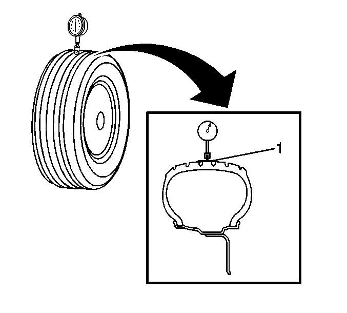
- Wrap the circumference of each tire with tape (1) in the center tread area.
Wrapping the tread with tape allows for a smooth and accurate reading of radial runout to be obtained.
- Position the dial indicator on the taped portion of the tire tread such that the dial indicator is perpendicular to the tire tread surface.
- Slowly rotate the tire and wheel assembly one complete revolution in order to find the low spot.
- Set the dial indicator to zero at the low spot.
- Slowly rotate the tire and wheel assembly one more complete revolution and
measure the total amount of radial runout.
Specification
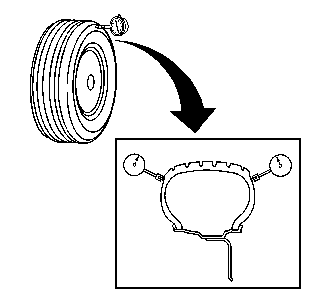
Maximum tire and wheel assembly radial runout – measured on-vehicle: 1.52 mm (0.060 in) - Position the dial indicator on a smooth portion of the tire sidewall, as close to the tread as possible, such that the dial indicator is perpendicular to the tire sidewall surface.
- Slowly rotate the tire and wheel assembly one complete revolution in order to find the low spot. Ignore any jumps or dips due to sidewall splices.
- Set the dial indicator to zero at the low spot.
- Slowly rotate the tire and wheel assembly one more complete revolution and
measure the total amount of lateral runout. Ignore any jumps or dips due to
sidewall splices and attain an average runout measurement.
Specification
Maximum tire and wheel assembly lateral runout – measured on-vehicle: 1.52 mm (0.060 in) - Repeat steps 4 through 12 until all of the tire and wheel assembly radial and lateral runout measurements have been taken.
- Lower the vehicle.
 Tire and Wheel Assembly Runout Measurement - Off Vehicle
Raise and support the vehicle.
Mark the location of the wheels to the wheel studs and mark the specific
vehicle position on each tire and wheel – LF, LR, RF, RR.
Remove the tire and wheel ...
 Tire and Wheel Assembly-to-Hub/Axle Flange Match-Mounting
Note: After remounting a tire and wheel assembly to a hub/axle flange,
remeasure the tire and wheel assembly on-vehicle runout in order to verify that
the amount of runout has been reduced an ...
Other materials:
Rear Seat Back Cushion Removal and Installation (60%)
Rear Seat Back Cushion Removal and Installation
Callout
Component Name
Preliminary Procedure
Remove the rear seat cushion. Refer to Rear Seat Cushion Removal
and Installation.
Remove the rear seat center retractor side be ...
Parking Brake Adjustment (Disc Brake)
Note: The park brake cable adjusting nut is a nylon lock type. Use
ONLY HAND TOOLS whenever tightening or loosening the adjusting nut.
Apply and fully release the park brake several times. Verify that the park
brake lever releases completely.
Turn ON the ignition. Verify the red B ...
Antilock Brake System Automated Bleed
Warning: Refer to Brake Fluid Irritant Warning.
Caution: Refer to Brake Fluid Effects on Paint and Electrical Components
Caution.
Note: Before performing the Antilock Brake System (ABS) Automated
Bleed Procedure, first perform a pressure bleed of the base brake system. Refer
...

0.0098