Chevrolet Sonic Repair Manual: Transmission Replacement
- Removal Procedure
-
- Remove the battery and battery tray. Refer to Battery Tray Replacement.
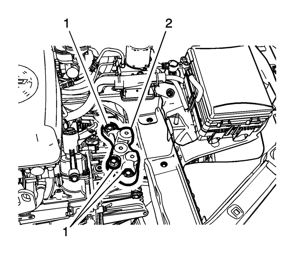
- Disconnect the transmission range selector lever cable terminal (1) from the transmission manual pin.
- Press the locking tab forward in order to release the transmission range selector lever cable (2) from the cable bracket.
- Disconnect the vehicle speed sensor and back-up light switch.
- Remove the wiring harness clips from the transmission.
- Remove the clutch actuator feed line clip.
- Remove the line from the clutch actuator cylinder pipe elbow.
- Install the engine support fixture. Refer to Engine Support Fixture.
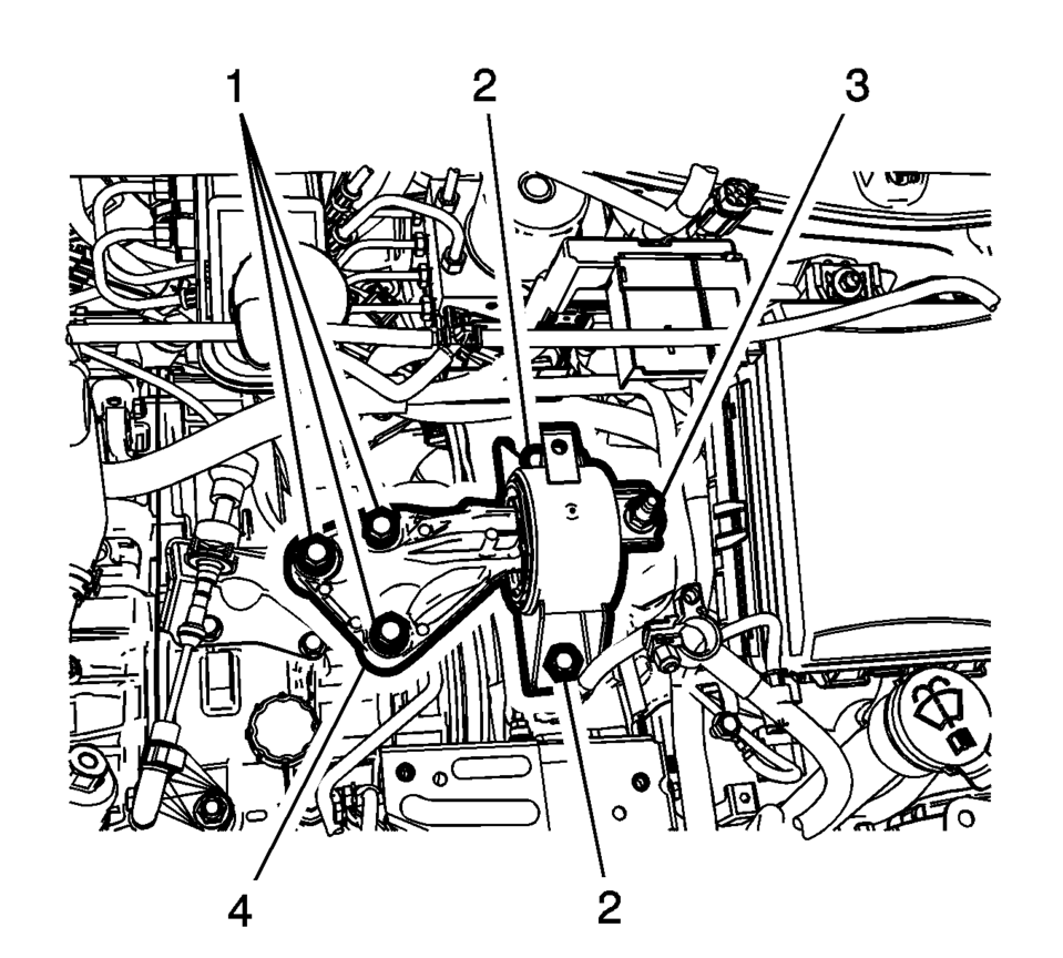
- Remove the transmission mount to body bolts (2) and nut (3).
- Remove the transmission mount bracket to transmission bolts (1) and remove transmission mount and bracket assembly.
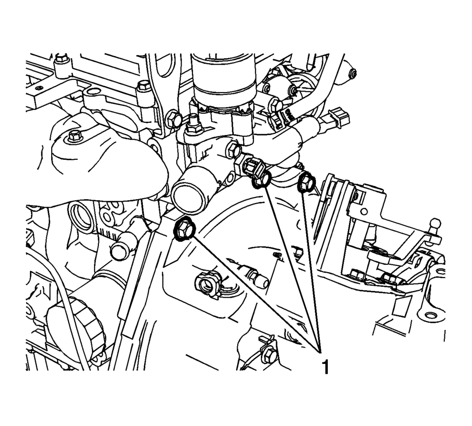
- Remove the 3 transmission to engine bolts (1).
- Disconnect the intermediate steering shaft from the steering gear. Refer to Intermediate Steering Shaft Replacement.
- Support the CRFM from the top.
- Raise the vehicle on a hoist. Refer to Lifting and Jacking the Vehicle.
- Remove the skid plate from the front frame, if equipped.
- Remove the left and right front wheelhouse liner inner front extensions. Refer to Front Wheelhouse Liner Inner Front Extension Replacement.
- Disconnect the hydraulic power steering hoses from the front frame, if equipped.
- Disconnect the exhaust isolators from the front suspension frame.
- Remove the drivetrain and front suspension frame. Refer to Drivetrain and Front Suspension Frame Replacement.
- Remove the wheel drive shafts from the transmission and intermediate shaft and support.
- Remove the wheel drive intermediate shaft. Refer to Front Wheel Drive Intermediate Shaft Replacement.
- Support the transmission with a suitable jack.
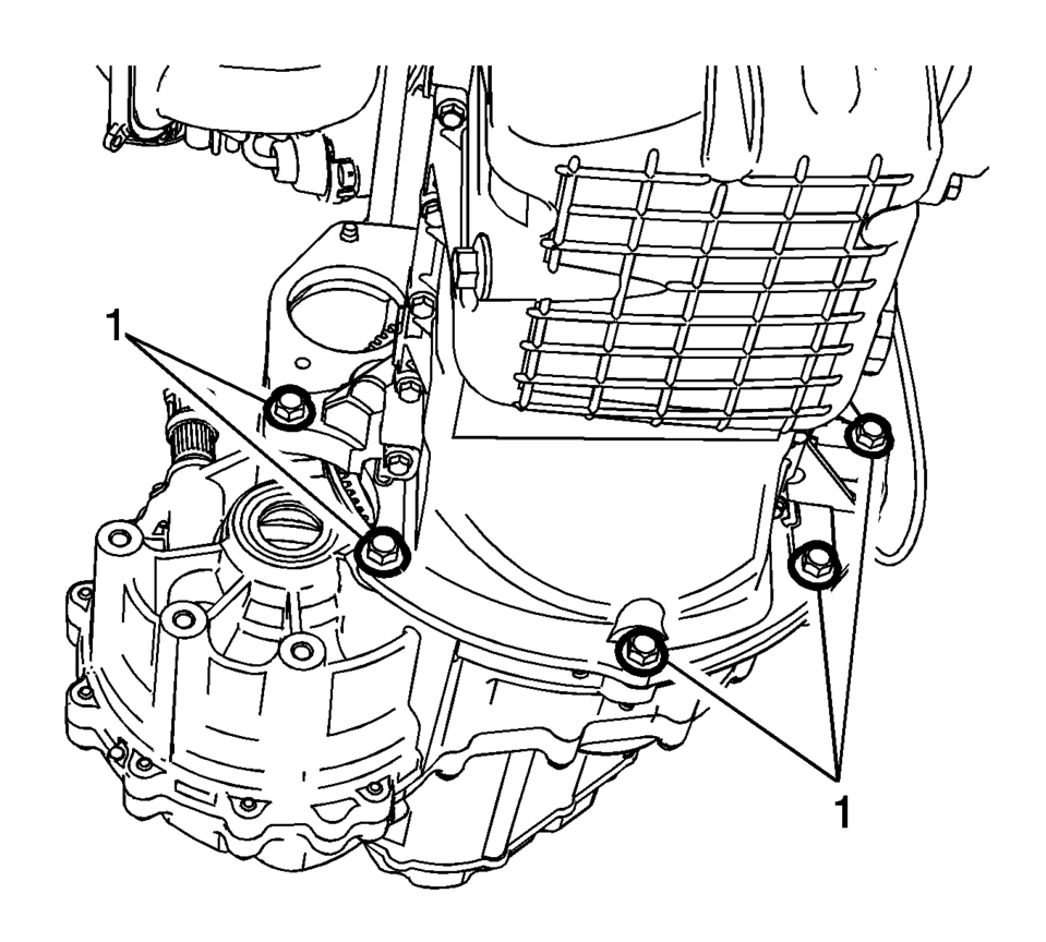
- Remove the lower oil pan to transmission bolts (1).
- Separate the transmission from the engine and lower the transmission from the vehicle.

- Installation Procedure
-
- Clean the clutch hub and the input shaft from any debris and contaminates with a lint-free towel.
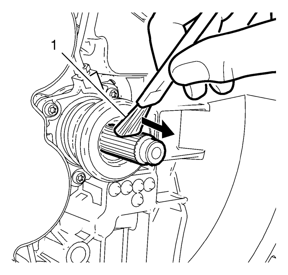
- Use a clean flat brush (1) to apply very light coating of multi-purpose grease to input shaft until the metal is only shiny . No visible clumps of grease are permissible regardless of size. Smear away from the transmission in direction of the shown arrow.
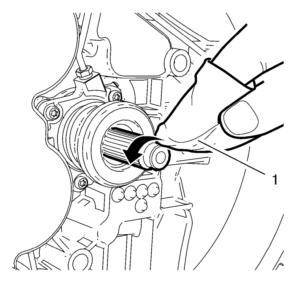
- Clean the entire lead surface of the input shaft with a NEW, lint-free towel (1).
- Raise the transmission into the vehicle and install the transmission to the engine.
- Install the lower oil pan to transmission bolts (1)
and tighten to 40 Y (30 lb ft)
.
- Remove the transmission jack.
- Install the wheel drive intermediate shaft. Refer to Front Wheel Drive Intermediate Shaft Replacement.
- Install the front wheel drive shafts to the transmission and intermediate shaft.
- Install the drivetrain and front suspension frame. Refer to Drivetrain and Front Suspension Frame Replacement.
- Connect the hydraulic power steering hoses to the front frame, if equipped.
- Install the rear transmission mount to the transmission. Refer to Transmission Rear Mount Replacement.
- Connect the exhaust isolators to the front suspension frame.
- Install the left and right front wheelhouse liner inner front extensions. Refer to Front Wheelhouse Liner Inner Front Extension Replacement
- Install the skid plate and fasteners to the front frame, if equipped.
Tighten the skid plate fasteners to 22 Y
(16 lb ft)
.
- Lower the vehicle.
- Connect the intermediate steering shaft to steering gear.
- Install the upper transmission to engine bolts (1) and tighten to
60 Y (44 lb ft)
.
- Install transmission bracket and mount assembly and install mount to
body bolts (2) and nut (3). Tighten the bolts and nut to 58 Y
(43 lb ft)
.
- Install the transmission bracket bolts (1) and tighten to 100 Y
(74 lb ft)
.
- Remove the engine support fixture.
- Install the feed line to clutch actuator cylinder pipe elbow.
- Install the wire harness clips to the transmission.
- Connect the backup light switch and vehicle speed sensor.
- Press the locking tab rearward in order to lock the transmission range selector lever cable (2) to the cable bracket.
- Connect the transmission range selector lever cable terminals (1) to the transmission manual pins.
- Install the battery and battery tray. Refer to Battery Tray Replacement
- Connect the negative battery cable. Refer to Battery Negative Cable Disconnection and Connection.
- Bleed the clutch system. Refer to Hydraulic Clutch System Bleeding.
Warning:
Use care when cleaning the clutch hub. The clutch hub may have sharp edges and can cause personal injury if contact is made. Wear protective gloves to avoid personal injury.
Caution:
Applying too much or the wrong type of grease on the transmission input shaft may cause damage, clutch slippage or failure. Always apply the correct type of grease. Never apply more grease than is necessary to coat the transmission input shaft with a very thin film of grease.
Caution:
Ensure that no grease remains on the lead surface of the transmission input shaft. Clean the lead surface of the transmission input shaft prior to the assembly of the transmission to the engine. Failure to maintain a clean surface may cause clutch slippage or failure.
Caution:
Refer to Fastener Caution
 Transmission Rear Mount Replacement
Removal Procedure
Raise and support the vehicle. Refer to
Lifting and Jacking the Vehicle.
Using a suitable jack stand, support the rear of the
powertrain.
Remove a ...
 Transmission System Description and Operation
The F17 is a 5 speed manual transmission assembly.
Note: Use only transmission fluid listed within the
Adhesives, Fluids, Lubricants, and Sealers for
this manual transmission assemb ...
Other materials:
Lock, Unlock Settings
Select and the following may display:
Remote Unlock Light Feedback
Remote Lock Light & Horn Feedback
Remote Door Unlock
Remote Unlock Light Feedback When on, the exterior lamps will flash when unlocking
the vehicle with the RKE transmitter.
Select Flash Lights or Lights Off.
Remot ...
Blizzard Conditions
Being stuck in snow can be a serious situation. Stay with the vehicle unless
there is help nearby. If possible, use Roadside Assistance. See Roadside Assistance
Program. To get help and keep everyone in the vehicle safe:
Turn on the hazard warning flashers.
Tie a red cloth to an outside mi ...
Front Side Door Lock Cylinder Coding (Free Wheeling)
Special Tools
BO-49753 Assembly Tool
The door lock cylinder uses 8 of the 8?€‰cut positions. The tumbler positions
are staggered from side to side, 4 on one side and 4 on the other, are not self-retaining,
and are not snap in.
Note: All lock cylinders for side milled keys ha ...

0.0078