Chevrolet Sonic Repair Manual: Body Hinge Pillar Lower Reinforcement Replacement
- Removal Procedure
-
- Disable the SIR system. Refer to SIR Disabling and Enabling.
- Disconnect the negative battery cable. Refer to Battery Negative Cable Disconnection and Connection.
- Remove all related panels and components.
- Repair as much of the damage as possible. Refer to Dimensions - Body.
- Remove the sealers and anti-corrosion materials from the repair area. Refer to Anti-Corrosion Treatment and Repair.
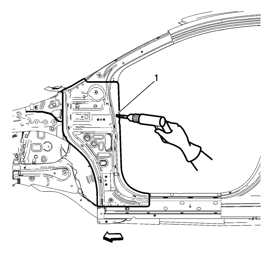
- Locate and mark all the necessary factory welds of the front hinge pillar body.
- Drill all factory welds (1). Note the number and location of welds for installation of the service assembly.
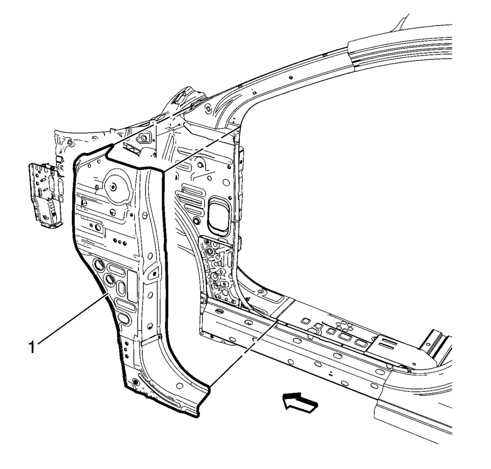
- Remove the damaged front hinge pillar body reinforcement (1).
Warning:
Refer to Approved Equipment for Collision Repair Warning.
- Installation Procedure
-
- Prepare all mating surfaces as necessary.
- Align the front hinge pillar body reinforcement.
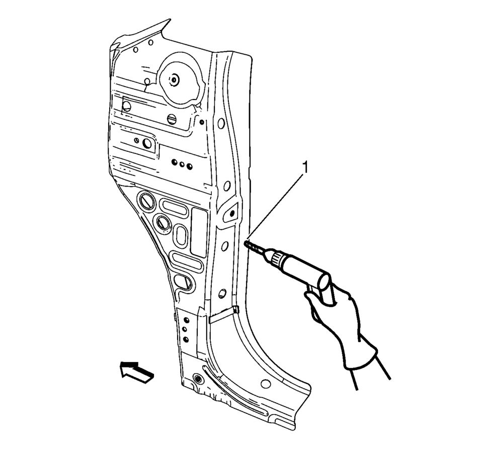
- Drill 8 mm (5/16 in)
holes for plug welding along the edges of the front hinge pillar body as noted from the original panel (1).
- Clean and prepare the attaching surfaces for welding.
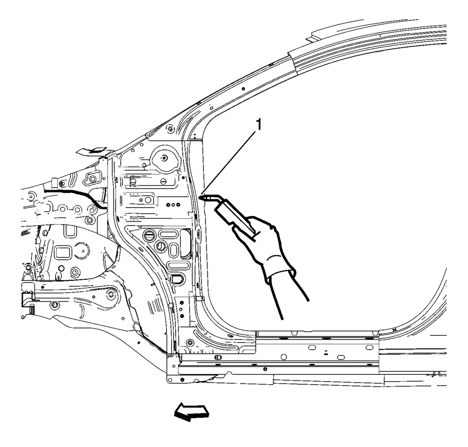
- Position the front hinge pillar body reinforcement on the vehicle (1).
- Verify the fit of the front hinge pillar body reinforcement.
- Clamp the front hinge pillar body reinforcement into position.
- Plug weld accordingly (1).
- Apply the sealers and anti-corrosion materials to the repair area, as necessary. Refer to Anti-Corrosion Treatment and Repair.
- Paint the repaired area. Refer to Basecoat/Clearcoat Paint Systems.
- Install all related panels and components.
- Connect the negative battery cable. Refer to Battery Negative Cable Disconnection and Connection.
- Enable the SIR system. Refer to SIR Disabling and Enabling.
 General
...
 Body Waterleak Repair
Warning: If the vehicle interior is exposed to moisture and becomes
soaked up to the level of the sensing and diagnostic module (SDM), the SDM and
SDM harness connector must be replaced. ...
Other materials:
Front Wheelhouse Liner Replacement (Rear)
!l
Front Wheelhouse Liner Replacement
Callout
Component Name
Preliminary Procedure
Remove the tire and wheel assembly. Refer to Tire and Wheel Removal and
Installation.
1
Front Wheelhouse Rear Li ...
Starter Replacement (LUW)
Removal Procedure
Disconnect the negative battery cable. Refer to Battery Negative Cable
Disconnection and Connection.
Raise and support the vehicle. Refer to Lifting and Jacking the Vehicle.
Remove the drivetrain and front suspension frame skid plate. Refer to
Drivet ...
Transmission Rear Mount Replacement
Removal Procedure
Raise and support the vehicle. Refer to
Lifting and Jacking the Vehicle.
Remove and DISCARD the rear transmission mount bracket
to rear mount through bolt (1).
Remove rear transmission mount to frame bolt (3).
Push and hold ...

0.0065