Chevrolet Sonic Repair Manual: Brake Pedal Travel Measurement and Inspection
Special Tools
CH-28662 Brake Pedal Effort Gauge
For equivalent regional tools, refer to Special Tools.
- With the ignition OFF and the brakes cool, apply the brakes 3–5 times, or until the brake pedal becomes firm, in order to deplete the brake booster power reserve.
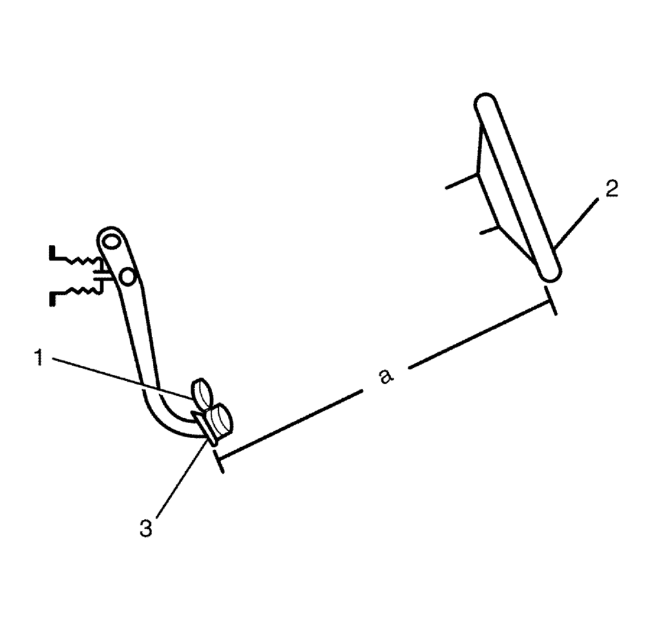
- Install the CH-28662 gauge (1), or equivalent, to the brake pedal (3).
- Measure and record the distance (a) from the brake pedal (3) to the rim of the steering wheel (2). Note the points of measurement.
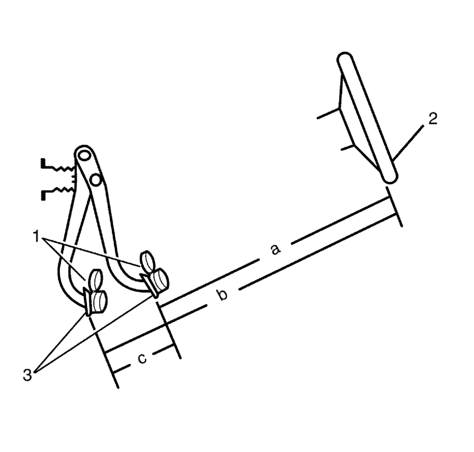
- Apply and maintain a force of 445 N (100 lb) to the brake pedal, as indicated on the CH-28662 gauge (1), or equivalent.
- While maintaining 445 N (100 lb) of force to the brake pedal (3), measure and record the distance (b) from the same point on the brake pedal (3) to the same point on the rim of the steering wheel (2).
- Release the brake pedal (3) and repeat steps 4 and 5 to obtain a second measurement. After obtaining a second measurement, proceed to step 7.
- Average the first and second measurements recorded for the 2 applies of the brakes.
- Subtract the initial unapplied distance (a), from the average applied distance (b)
to obtain the brake pedal travel measurement (c).
Specification
Maximum brake pedal travel – measured with the ignition OFF, brake booster power assist depleted, and the brakes cool.
 Brake Pedal Pushrod Inspection
Disconnect the brake pedal pushrod (2) from the brake pedal.
Reposition the pedal pushrod boot (1) toward the front of the vehicle to
expose as much of the pedal pushrodR ...
 Parking Brake
...
Other materials:
Halogen Bulb Warning
Warning: Halogen bulbs contain gas under pressure. Handling a bulb
improperly could cause it to shatter into flying glass fragments. To help avoid
personal injury:
Turn off the lamp switch and allow the bulb to cool before changing
the bulb.
Leave the lamp switch OFF until th ...
Exhaust Heat Shield Replacement
Exhaust Heat Shield Replacement
Callout
Component Name
Preliminary Procedure
Disconnect the exhaust system hangers and allow the exhaust system to
rest on the rear axle.
1
Exhaust Heat Shield Fa ...
Car phone or CB radio
When installing a car phone or CB radio system in your Nissan Armada, it is essential
to follow proper installation guidelines. Incorrect installation may interfere with
the vehicle’s electronic control modules and wiring systems, potentially affecting
performance and safety.
WARNING
Us ...

0.0114