Chevrolet Sonic Repair Manual: Camshaft Position Actuator Adjuster Installation
Special Tools
- EN-6340 Camshaft Adjuster Locking Tool
- EN-6628-A Camshaft Locking Tool
- EN-45059 Angle Meter
For equivalent regional tools, refer to Special Tools.
- Turn the camshaft by the hexagon until the groove on the end of the camshafts is horizontal.
- Install the EN-6628-A locking tool (1).
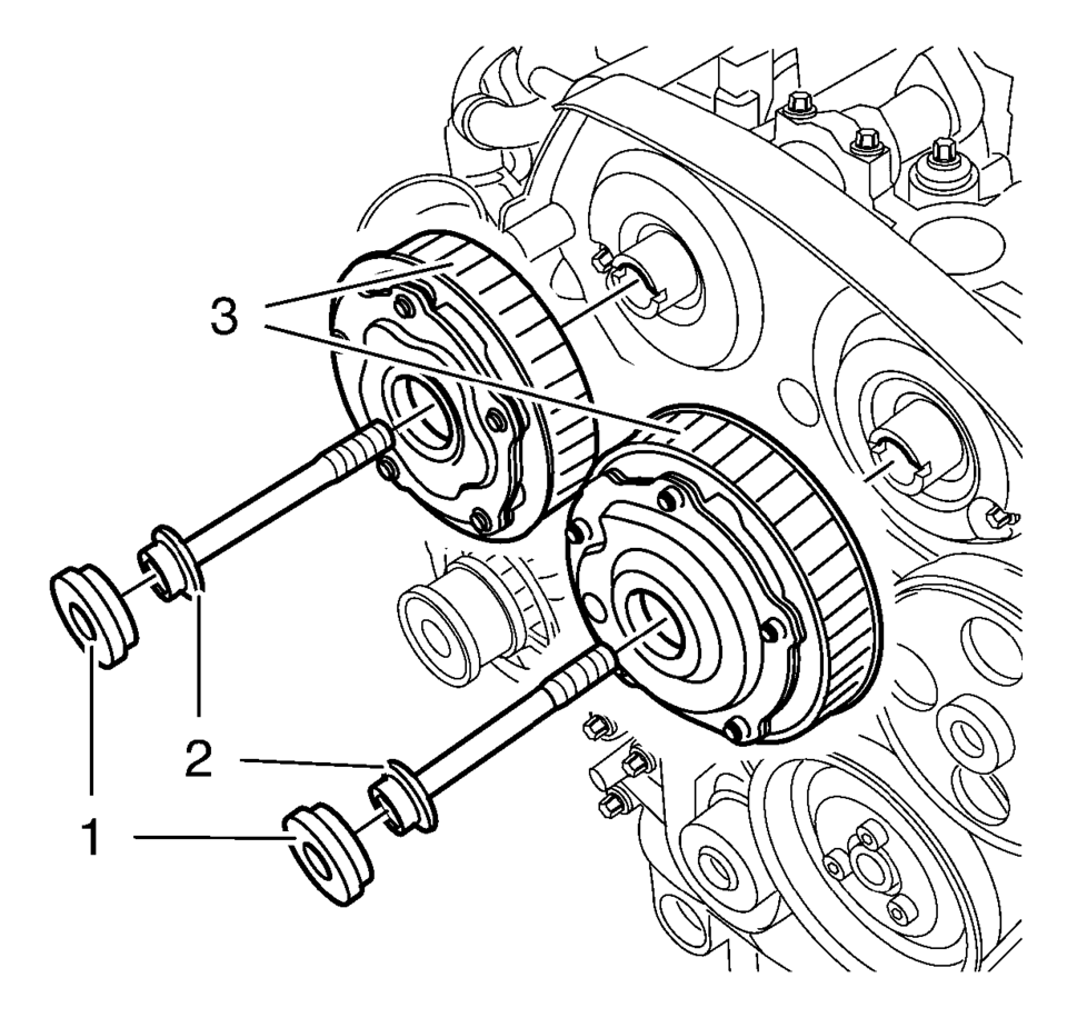
- Install intake camshaft position actuator adjuster and/or the exhaust camshaft position actuator adjuster (3).
- Install a NEW intake camshaft position actuator adjuster bolt and/or a NEW exhaust camshaft position actuator adjuster bolt (2). DO NOT tighten the bolts yet.
- Install the EN-6340 locking tool into the camshaft position actuator adjusters.
- Install the EN-6340-left locking tool (1) in the camshaft position actuator adjusters as shown.
- Install the EN-6340-right locking tool (2) in the camshaft position actuator adjusters as shown.
- Install the camshaft position actuator adjuster bolts (2) and tighten the bolts in 3 passes using the EN-45059 meter.
- First pass to 50 Y (37 lb ft)
- Second pass to an additional 150 degrees
- Final pass to an additional 15 degrees
- Install the 2 camshaft position actuator adjuster closure plugs (1) and
tighten to 30 Y (22 lb ft)
.
- Remove the EN-6628-A locking tool.
- After the installation of the timing belt, rotate the engine 720 degrees and check the position of the crankshaft and camshafts, again. Refer to Timing Belt Adjustment.
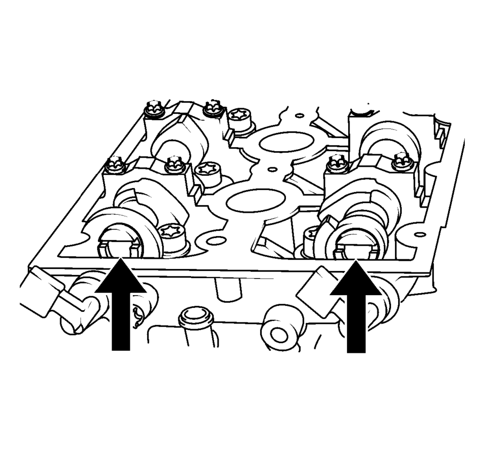
Note:
Note the arrows.

Note:
If the cover is contaminated with oil, you have to clean it close.
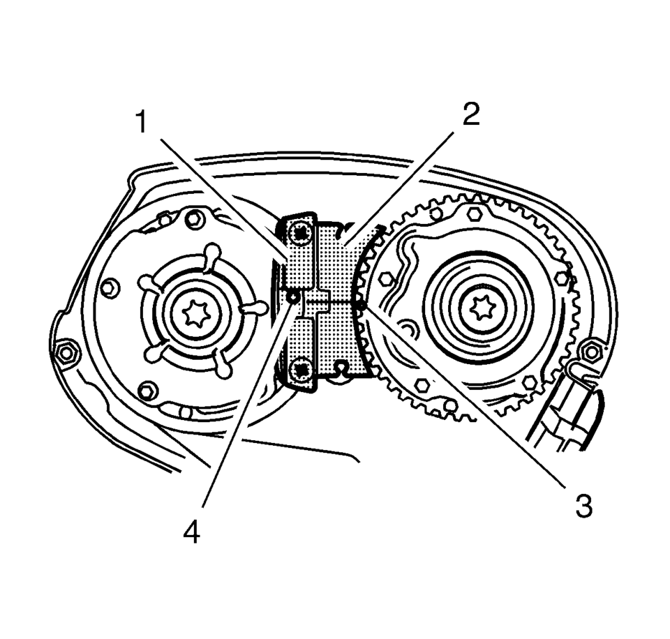
Note:
The spot type marking (4) on the intake camshaft position actuator adjuster does not correspond to the groove of EN-6340-left locking tool - left during this process but must be somewhat above as shown.
Note:
The spot type marking (3) on the exhaust camshaft position actuator adjuster must correspond to the groove on EN-6340-left locking tool - right.
Caution:
Refer to Fastener Caution.
Caution:
Refer to Torque-to-Yield Fastener Caution.
Note:
A second technician is required.
Note:
Use an appropriate open-end wrench in order to counterhold the camshaft hexagon. A thin cross-section wrench is required for a better fit. The usage of EN-6628-A locking tool is for the camshaft adjustment to prevent misalignment of the camshafts. The wrench is required to counterhold the camshafts during bolt torque procedure.
Note:
Check the closure bolt seal ring.
 Camshaft Intake and Exhaust Sprocket Replacement
Special Tools
EN-955-A Locking Pin
For equivalent regional tools, refer to Special Tools.
Removal Procedure
Remove the air cleaner assembly. Refer to Air Cleaner Assembly Replacemen ...
 Camshaft Position Actuator Adjuster Removal
Special Tools
EN-6340 Camshaft Adjuster Locking Tool
EN-6628-A Camshaft Locking Tool
For equivalent regional tools, refer to Special Tools.
Note: The right half of the EN-6340 ...
Other materials:
Rear Brake Hose Replacement (Body to Axle - Disc Brake)
Removal Procedure
Warning: Refer to Brake Dust Warning.
Warning: Refer to Brake Fluid Irritant Warning.
Raise and support the vehicle. Refer to Lifting and Jacking the Vehicle.
Remove the tire and wheel assembly. Refer to Tire and Wheel Removal
and Install ...
Transmission Replacement (With 1.2L or 1.4L Engine)
Removal Procedure
Remove the battery tray. Refer to Battery Tray Replacement.
Without draining the coolant or removing the hoses, remove and position
aside the radiator surge tank. Refer to Radiator Surge Tank Replacement.
Remove the transmission range selector lever cabl ...
Clutch Actuator Cylinder Front Pipe Replacement
Removal Procedure
Remove the battery tray. Refer to Battery Tray Replacement.
Remove as much brake fluid out of brake fluid reservoir as possible.
Unclip the clutch actuator cylinder front pipe from the 2 retainers (1).
Remove the retaining ...

0.0072