Chevrolet Sonic Repair Manual: Charge Air Cooler Outlet Air Hose Replacement
- Removal Procedure
-
- Remove the front bumper fascia. Refer to Front Bumper Fascia Replacement.
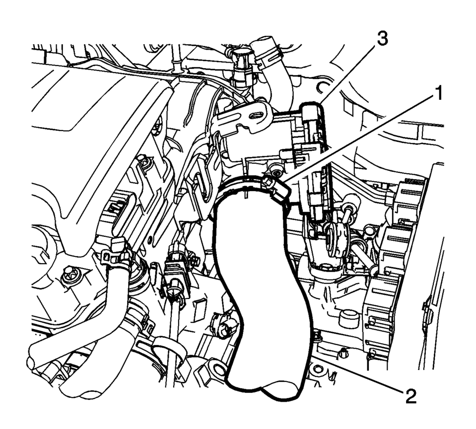
- Loosen the clamp (1) at the charge air cooler outlet pipe (2) to throttle body (3).
- Disconnect the intake air pressure and temperature sensor harness connector.
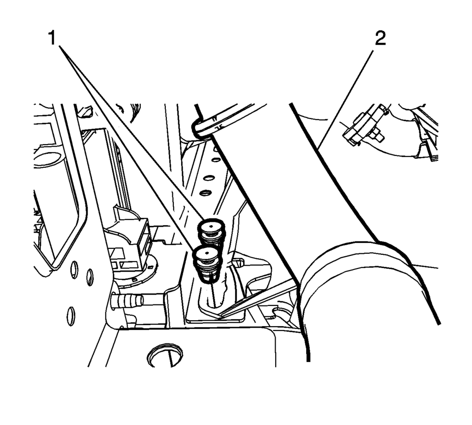
- Remove the plastic fasteners (1) from the charge air cooler outlet air pipe to frame bracket (2).
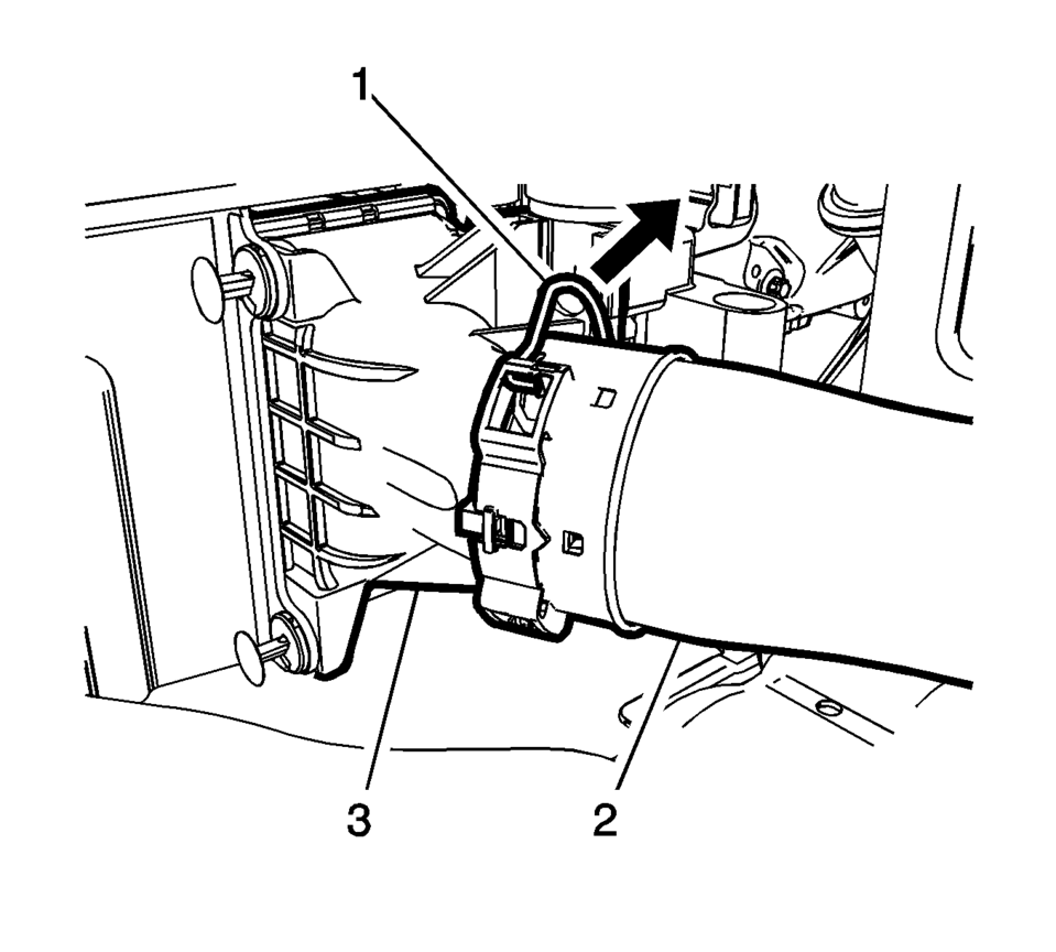
- Unclip the retainer spring (1).
- Remove the charge air cooler outlet air hose (2) from the charge air cooler (3).
- Transfer parts as necessary.
- Installation Procedure
-
- Install the charge air cooler outlet air hose (2) to charge air cooler (3).
- Clip the in retainer spring (1).
- Connect the intake air pressure and temperature sensor harness connector.
- Install the plastic fasteners (1) to the charge air cooler outlet air pipe to frame bracket (2).
- Install the charge air cooler inlet air pipe to the turbocharger.
- Tighten the clamp (1).
- Install the front bumper fascia. Refer to Front Bumper Fascia Replacement.
Caution:
Refer to Fastener Caution.
 Charge Air Cooler Inlet Air Hose Replacement
Removal Procedure
Disconnect the battery negative cable. Refer to Battery Negative Cable
Disconnection and Connection.
Remove the front bumper fascia. Refer to Front Bumper Fascia ...
 Charge Air Cooler Replacement
Charge Air Cooler Replacement
Callout
Component Name
Preliminary Procedures
Disconnect the negative battery cable. Refer to Battery ...
Other materials:
Rear Seat Head Restraint Guide Replacement
Rear Seat Head Restraint Guide Replacement
Callout
Component Name
Preliminary Procedure
Remove the rear seat head restraint. Refer to Rear Seat Head Restraint
Replacement
1
Rear Seat Head Restra ...
Rear Seat Cushion Cover and Pad Replacement
Rear Seat Cushion Cover and Pad Replacement
Callout
Component Name
Preliminary Procedure
Remove the rear seat cushion. Refer to Rear Seat Cushion Removal and
Installation
1
Rear Seat Cushion Cov ...
Oil Pressure Relief Valve Replacement
Removal Procedure
Remove the oil pan. Refer to Oil Pan Replacement.
Remove the oil pressure relief valve closure bolt (1).
Remove the oil pressure relief valve assembly (2).
Separate the piston (3) and the spring (4).
Warning: Bod ...

0.0074