Chevrolet Sonic Repair Manual: Control Valve Body Cover Replacement
- Removal Procedure
-
- Disconnect the battery negative cable. Refer to Battery Negative Cable Disconnection and Connection.
- Raise and support the vehicle. Refer to Lifting and Jacking the Vehicle.
- Remove the front bumper fascia opening lower cover. Refer to Front Bumper Fascia Opening Lower Cover Replacement.
- Remove the front wheel house liner inner front extension. Refer to Front Wheelhouse Liner Inner Front Extension Replacement.
- Drain the transmission fluid.
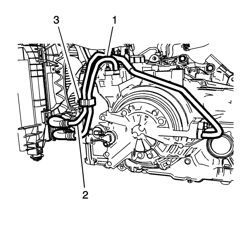
- Remove oil cooler inlet (1) and outlet (2) hoses from the retainer (3) on the control valve body cover.
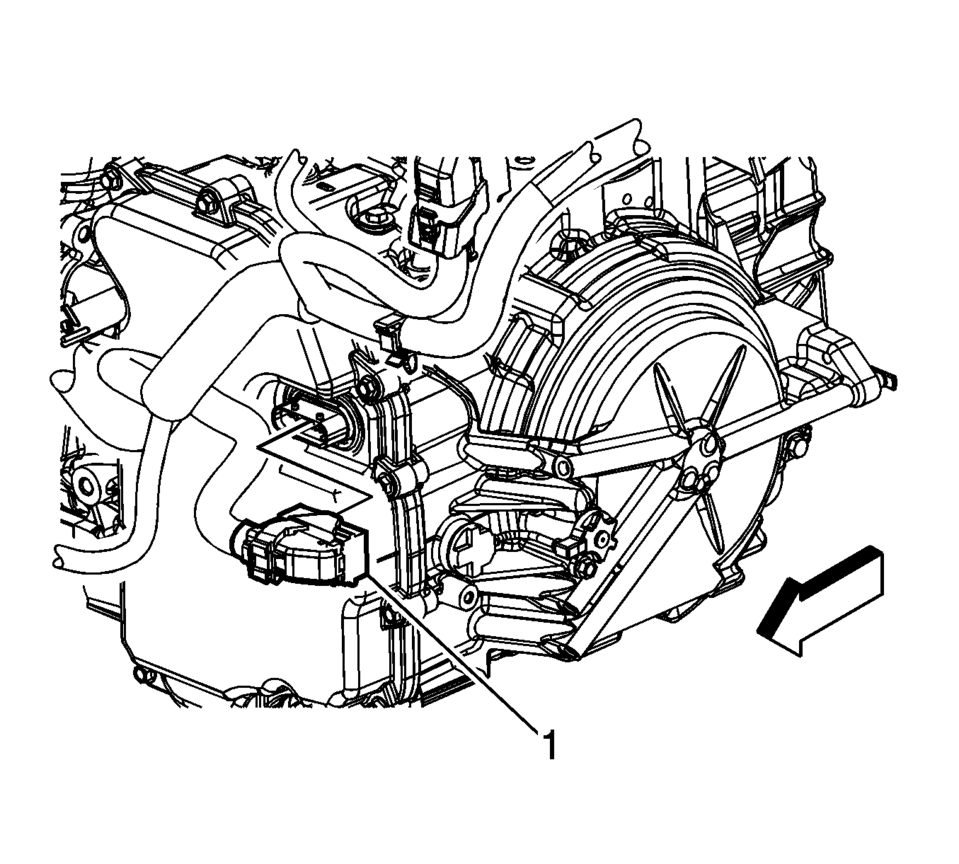
- Disconnect the control valve body transmission control module electrical connector (1), then unclip the wiring harness from the cover.
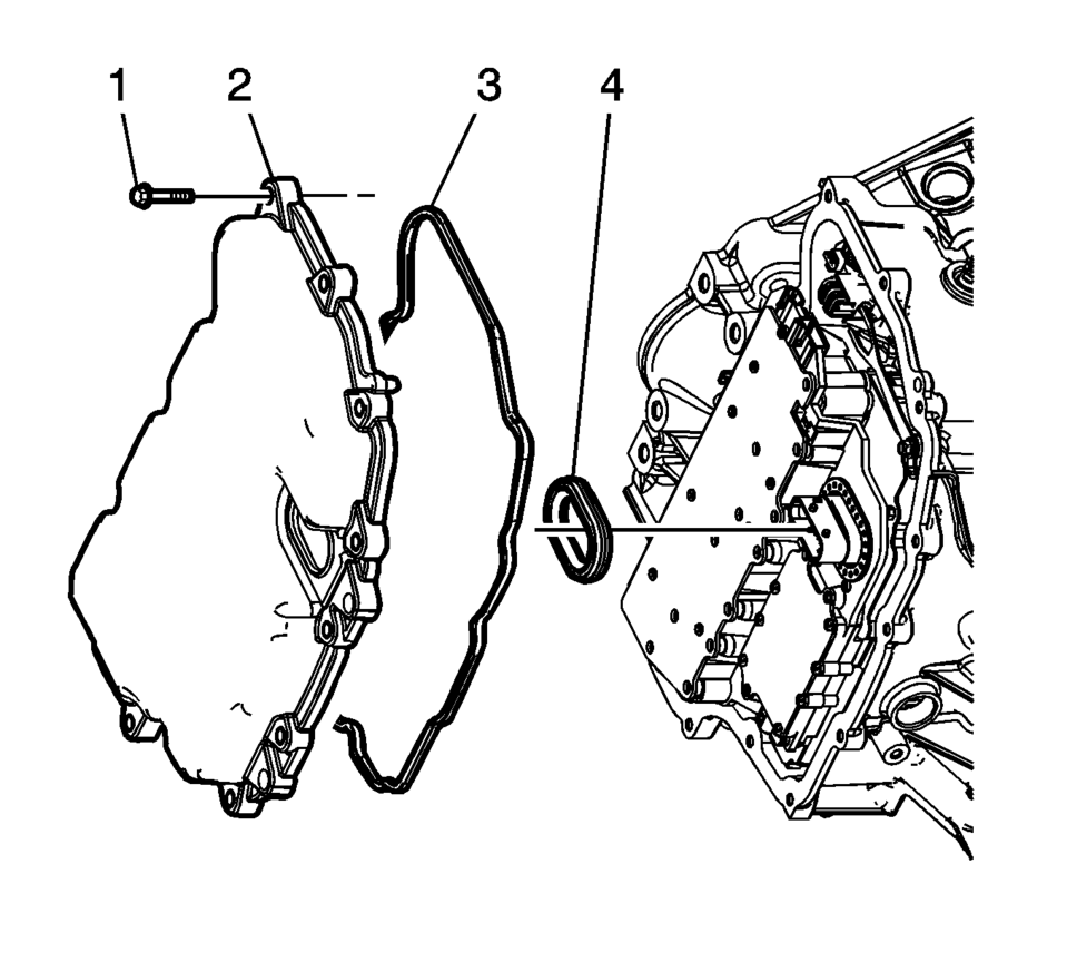
- Remove the control valve body cover bolts (1).
- Remove the control valve body cover (2).
- Remove the control valve body cover gasket (3).
- Remove the control valve body cover wiring connector hole seal (4).
- Remove all traces of the old gasket material. Clean the transmission case and control valve body cover gasket surfaces.
Caution:
Support the control solenoid valve assembly around the connector when removing the seal. Excessive pulling force can damage the internal electrical connections.
- Installation Procedure
-
- Install the control valve body cover wiring connector hole seal (4).
- Install the control valve body cover gasket (3) to the control valve body cover.
- Install the control valve body cover (2).
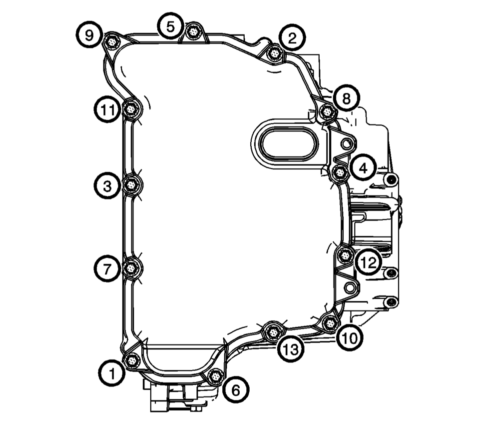
- Hand start the control valve body cover bolts (1).
- Install the control valve body cover bolts. Tighten
the bolts in sequence to 12 Y (106 lb in)
.
- Connect the control valve body transmission control module electrical connector (1), then clip the wiring harness to the cover.
- Raise the vehicle.
- Install the oil cooler inlet (1) and outlet (2) hoses to the retainer (3) on the control valve body cover.
- Install the front wheel house liner inner front extension. Refer to Front Wheelhouse Liner Inner Front Extension Replacement.
- Install the front bumper fascia opening lower cover. Refer to Front Bumper Fascia Opening Lower Cover Replacement.
- Fill the transmission with correct fluid.
- Check transmission fluid level. Refer to Transmission Fluid Level and Condition Check.
- Lower the vehicle.
- Connect the battery negative cable. Refer to Battery Negative Cable Disconnection and Connection.
- Check for leaks.
Caution:
Refer to Fastener Caution.
Note:
Install all control valve body cover bolts and studs by hand then torque all bolts and studs in sequence.
 Control Valve Body Cover Installation
Control Valve Body Cover Installation
Callout
Component Name
1
Input Speed Sensor Connector
2
...
 Control Valve Body Replacement
Control Valve Body Replacement
Callout
Component Name
Preliminary Procedure
Remove the control solenoid valve and transmission ...
Other materials:
Front Side Door Replacement
Front Side Door Replacement
Callout
Component Name
Warning: Refer to SIR Warning.
Preliminary Procedures
Mark the location of the hinge before removing the bolts with a
grease pencil.
Remove the front door ...
Strut and Shock Absorber Inspection
Note: The strut assembly DOES NOT have to be removed from the vehicle
to perform the following inspection procedure.
Note: A light film of oil on the top portion of the strut is normal.
DO NOT replace the strut for this condition.
Condition 1
Oil or fluid residue only o ...
Crankshaft Balancer Removal
Special Tools
EN-652 Flywheel Holder
For equivalent regional tools, refer to Special Tools.
Install the EN-652 holder (1). Lock the flywheel (2) or the automatic
transmission flex plate via the starter ring gear.
Remove and DISCARD the crankshaft balancer bo ...

0.0071