Chevrolet Sonic Repair Manual: Cylinder Head Replacement
Special Tools
- BO-38185 Hose Clamp Pliers
- EN-45059 Angle Meter
For equivalent regional tools, refer to Special Tools.
- Removal Procedure
-
- Disconnect the negative battery cable. Refer to Battery Negative Cable Disconnection and Connection.
- Relieve fuel system pressure. Refer to Fuel Pressure Relief.
- Disconnect the fuel feed pipe. Refer to Fuel Feed Pipe Replacement.
- Disconnect EVAP purge solenoid pipes from solenoid. Refer to Evaporative Emission System Hose/Pipe Replacement.
- Drain the cooling system. Refer to Cooling System Draining and Filling.
- Remove the coolant surge tank. Refer to Radiator Surge Tank Replacement.
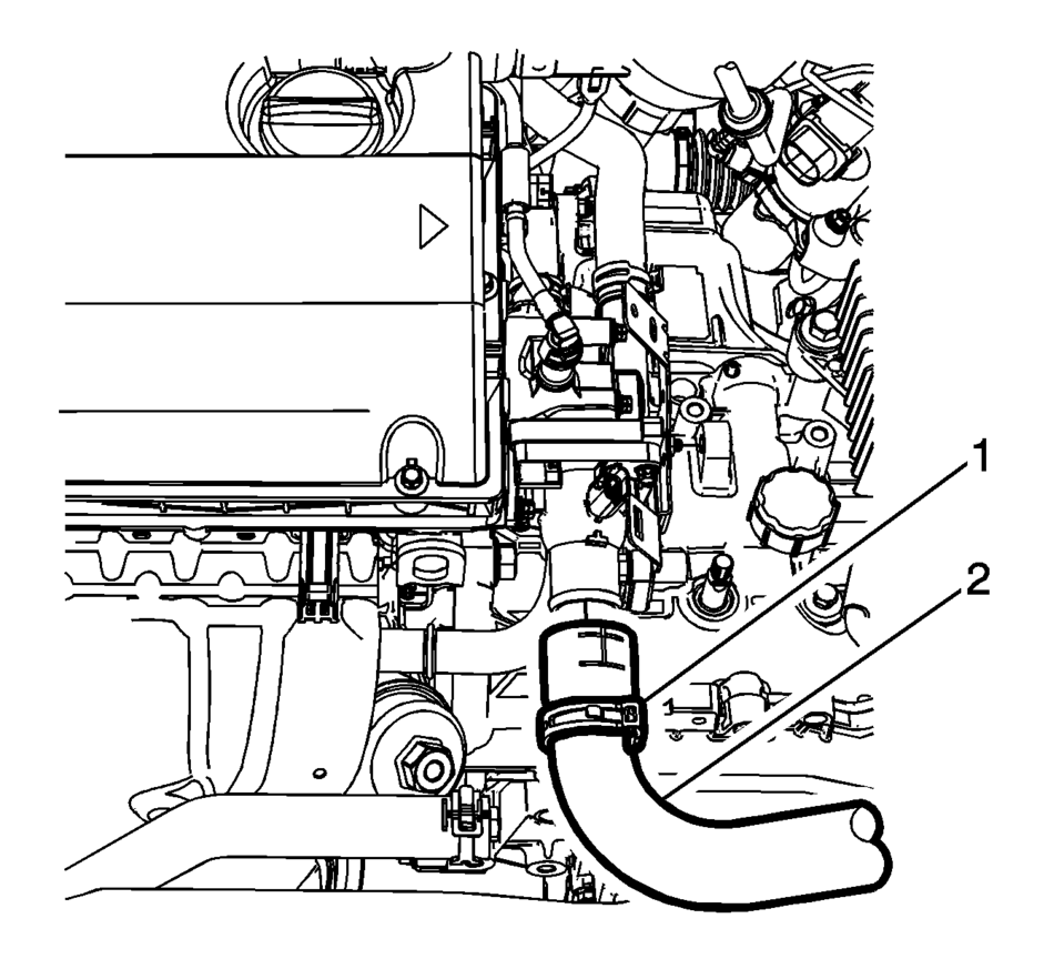
- Loosen the radiator inlet hose clamp (1) at the engine using BO-38185 pliers.
- Remove the radiator inlet hose (2) from the engine.
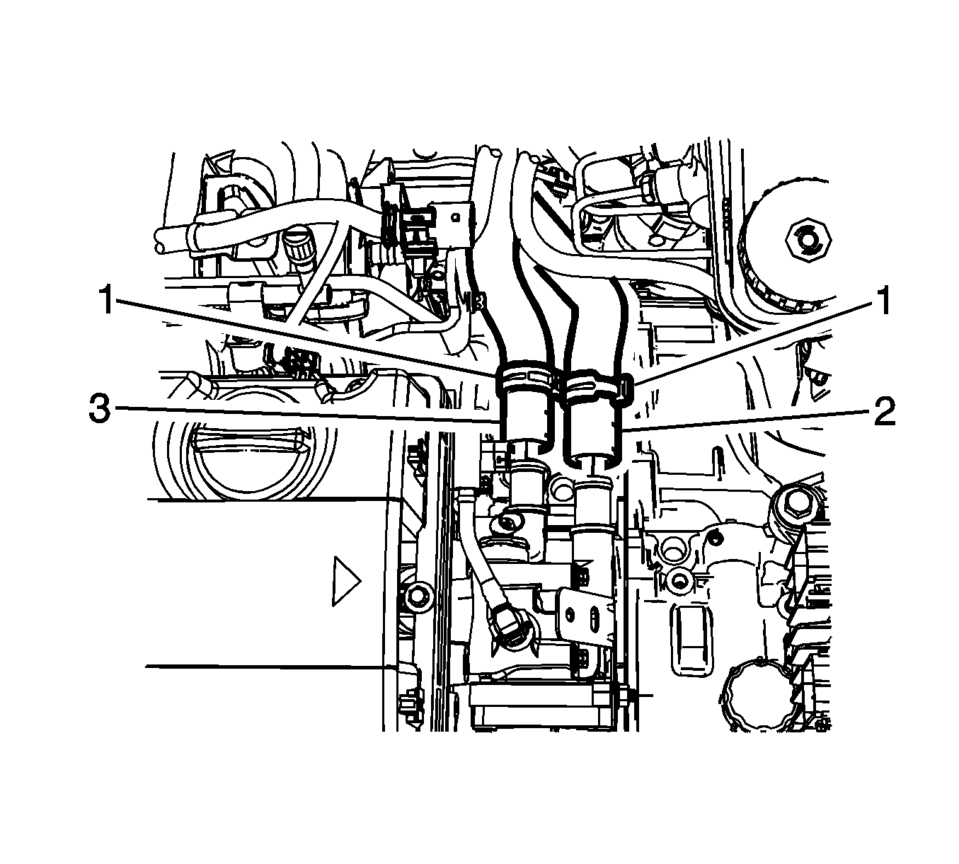
- Remove the inlet and outlet heater hose clamp (1) at the engine using BO-38185 pliers.
- Remove the inlet hose (2) and outlet (3) from the engine.
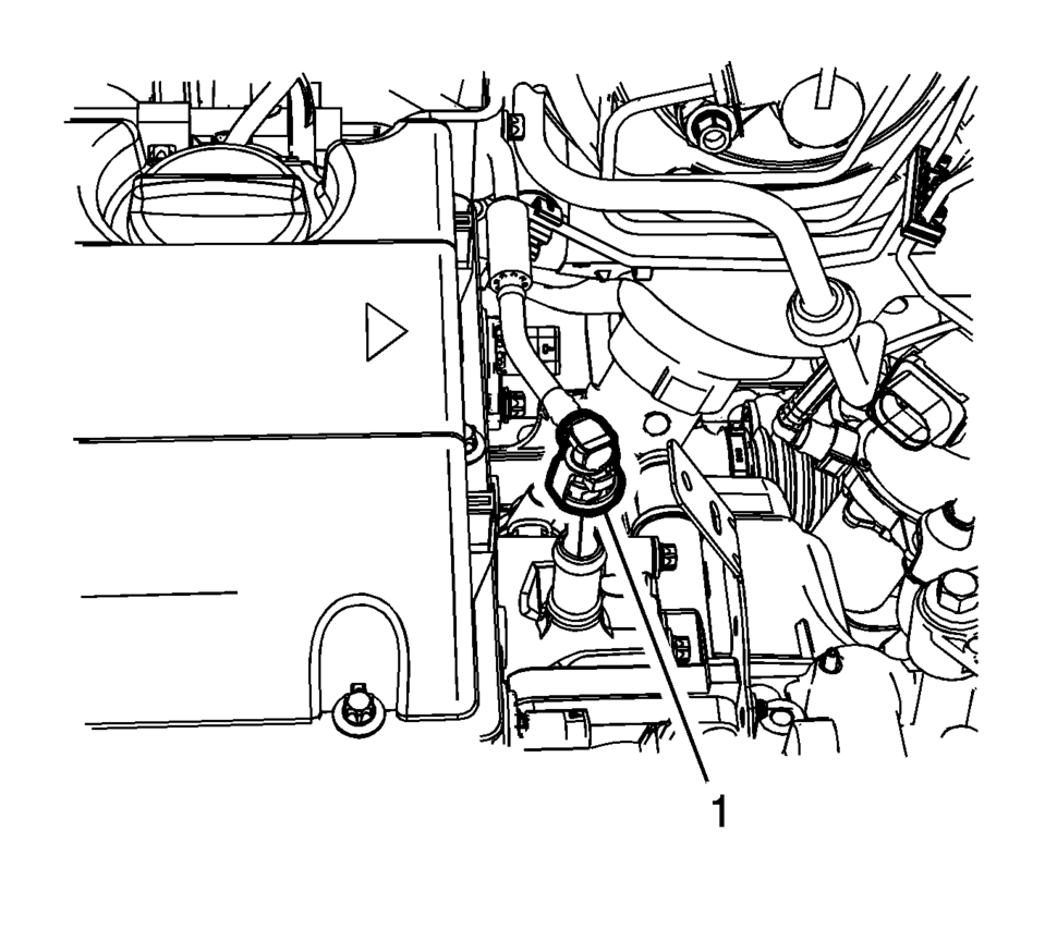
- Disconnect the throttle body heater inlet pipe (1).
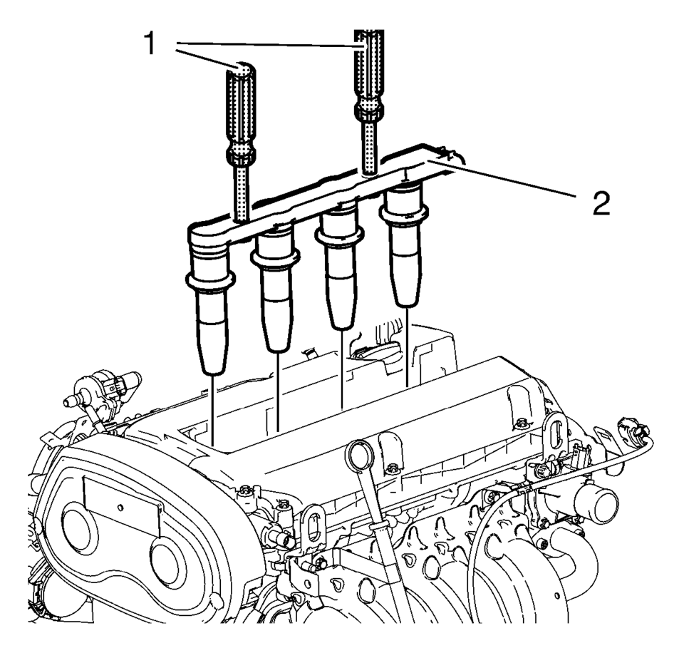
- Remove the ignition coil (2) . Refer to Ignition Coil Replacement.
- Disconnect PCV hose. Refer to Positive Crankcase Ventilation Hose/Pipe/Tube Replacement.
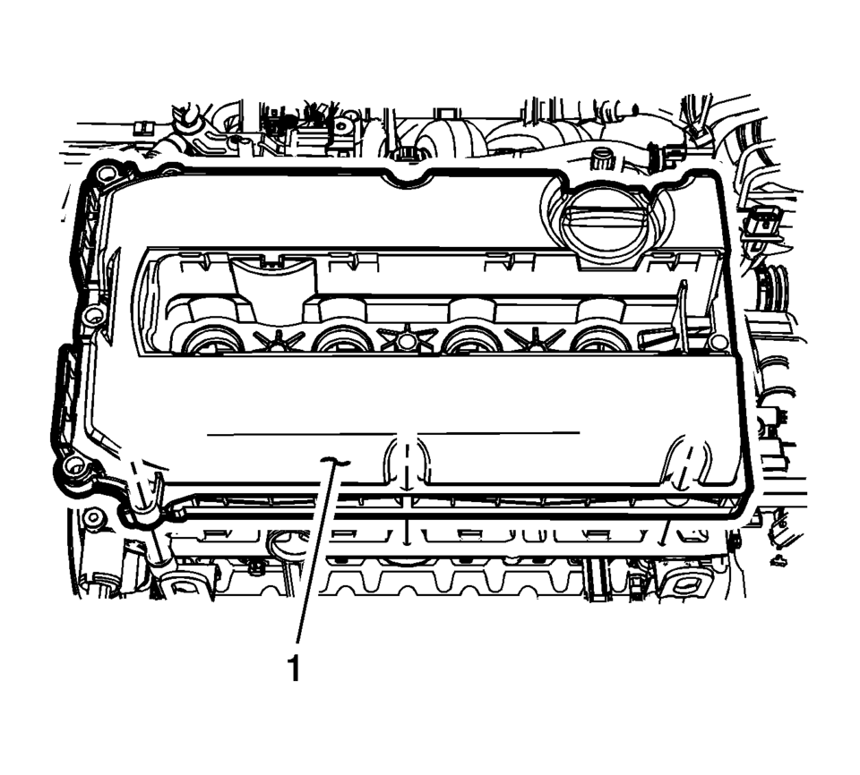
- Remove the camshaft cover (1). Refer to Camshaft Cover Replacement.
- Install engine support fixture. Refer to Engine Support Fixture.
- Remove the engine mount. Refer to Engine Mount Replacement.
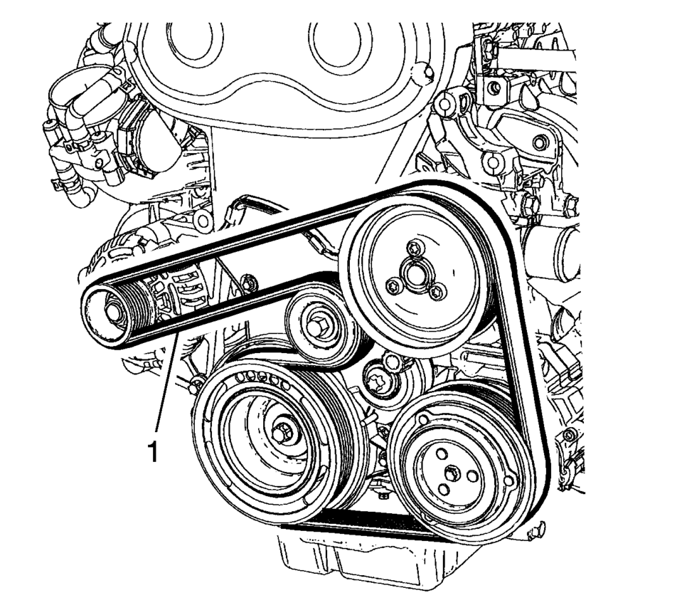
- Remove the drive belt (1). Refer to Drive Belt Replacement.
- Remove the engine mount bracket (1). Refer to Engine Mount Bracket Replacement.
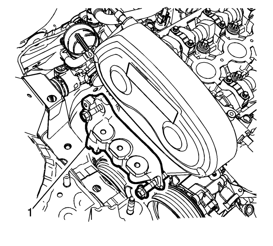
- Remove the upper timing cover (1). Refer to Timing Belt Upper Front Cover Replacement.
- Remove the timing belt center front cover. Refer to Timing Belt Center Front Cover Replacement.
- Raise the vehicle. Refer to Lifting and Jacking the Vehicle.
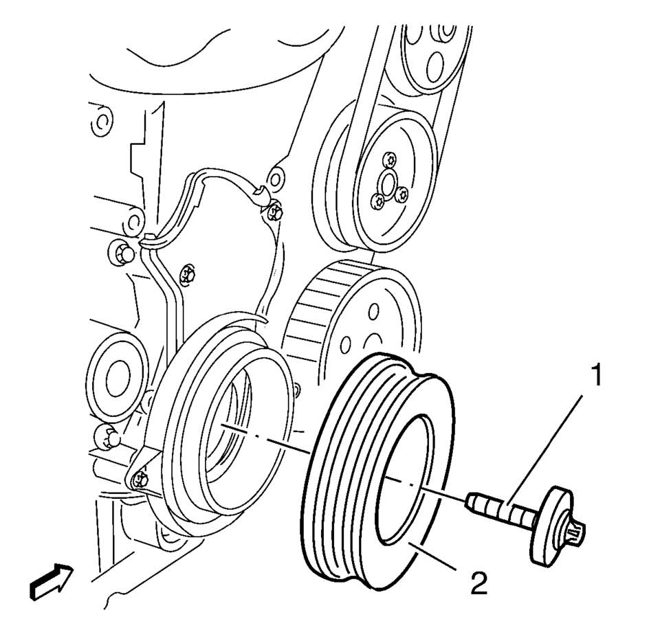
- Remove the crankshaft balancer (2). Refer to Crankshaft Balancer Replacement.
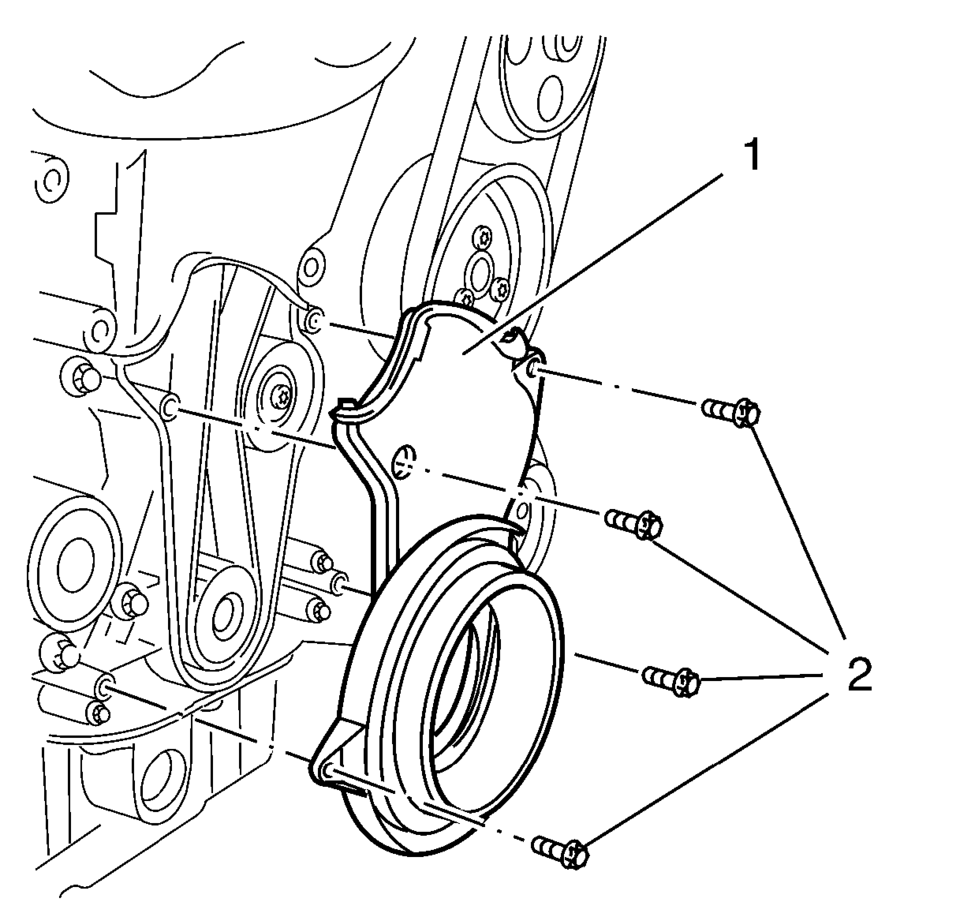
- Remove the timing belt lower front cover (1). Refer to Timing Belt Lower Front Cover Replacement.
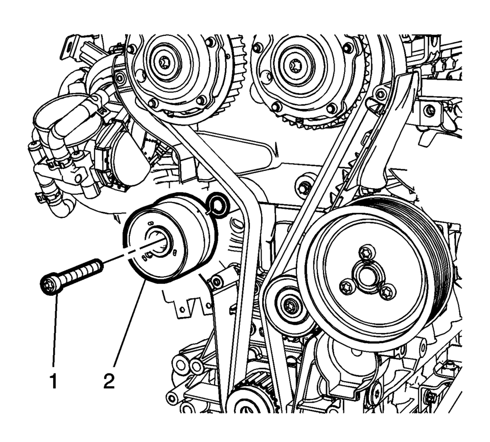
- Remove the timing belt tensioner bolt (1) and the timing belt tensioner (2). Refer to Timing Belt Tensioner Replacement.
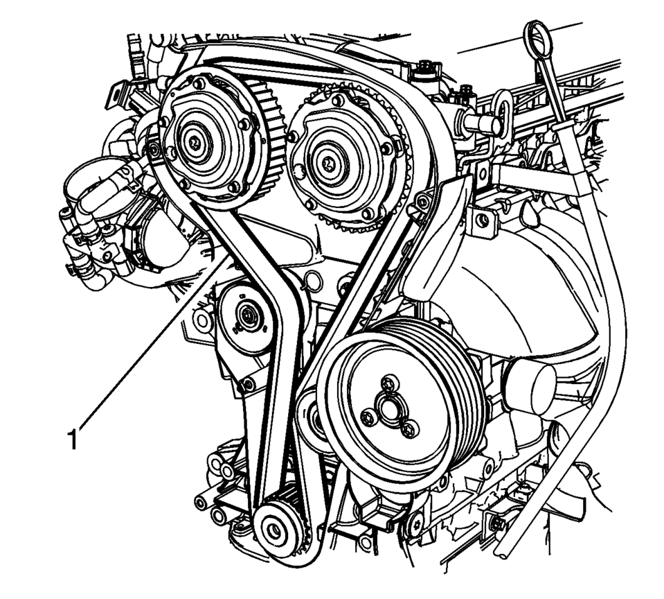
- Remove the timing belt (1). Refer to Timing Belt Replacement.
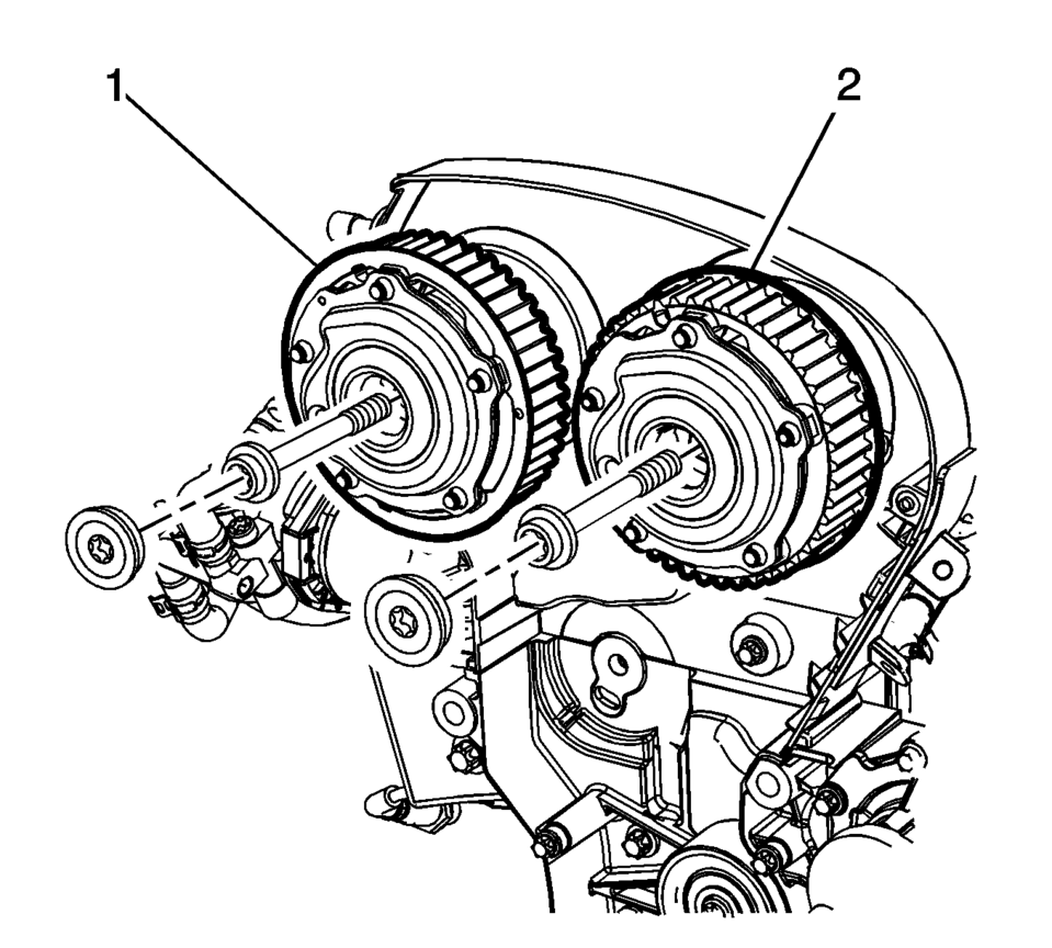
- Remove the camshaft sprocket intake (1) and exhaust (2). Refer to Camshaft Sprocket Replacement.
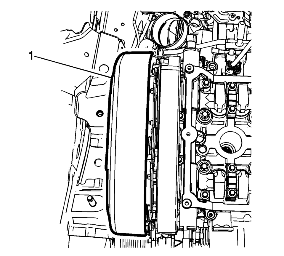
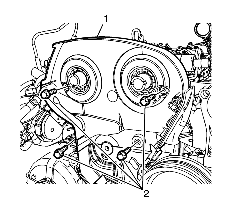
- Remove the timing belt rear cover (1). Refer to Timing Belt Rear Cover Replacement.
- Remove the exhaust manifold. Refer to Exhaust Manifold with Catalytic Converter Replacement.
- Place a floor jack with block of wood under the oil pan.
- Remove the engine support fixture. Refer to Engine Support Fixture.
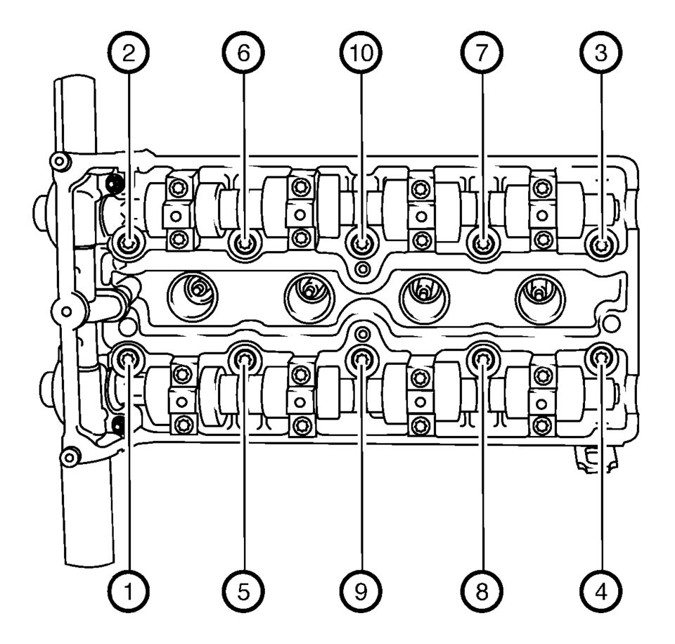
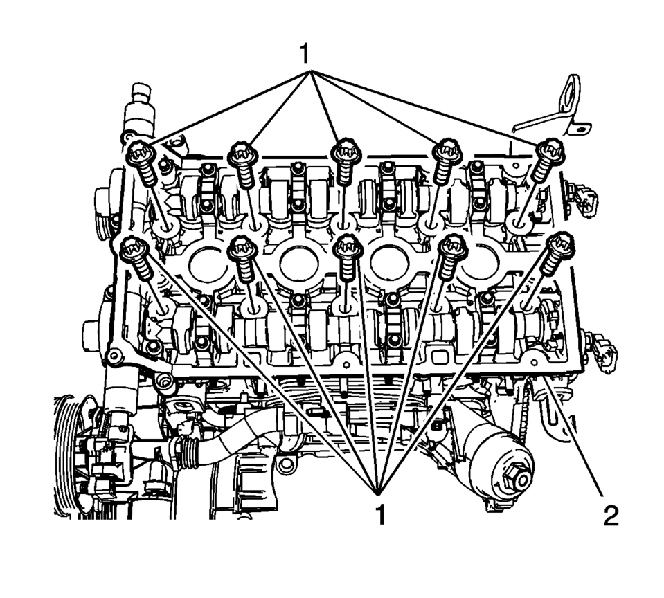
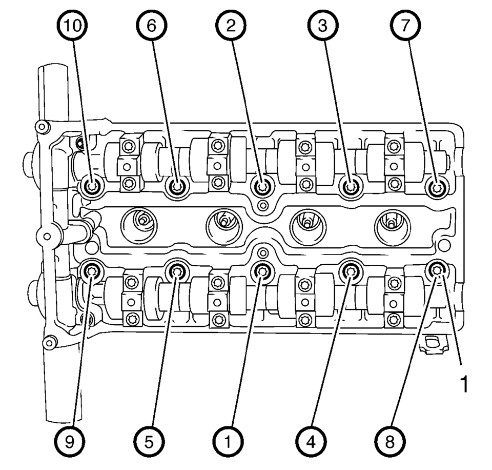
- Remove the ten cylinder head bolts in sequence as shown.
ii
Note:
Disconnect electrical and reposition harness and hose as necessary.
- Loosen the 10 bolts 90°.
- Loosen the 10 bolts 180°.
- Remove the cylinder head and place on a suitable base.
- Remove the cylinder head gasket.
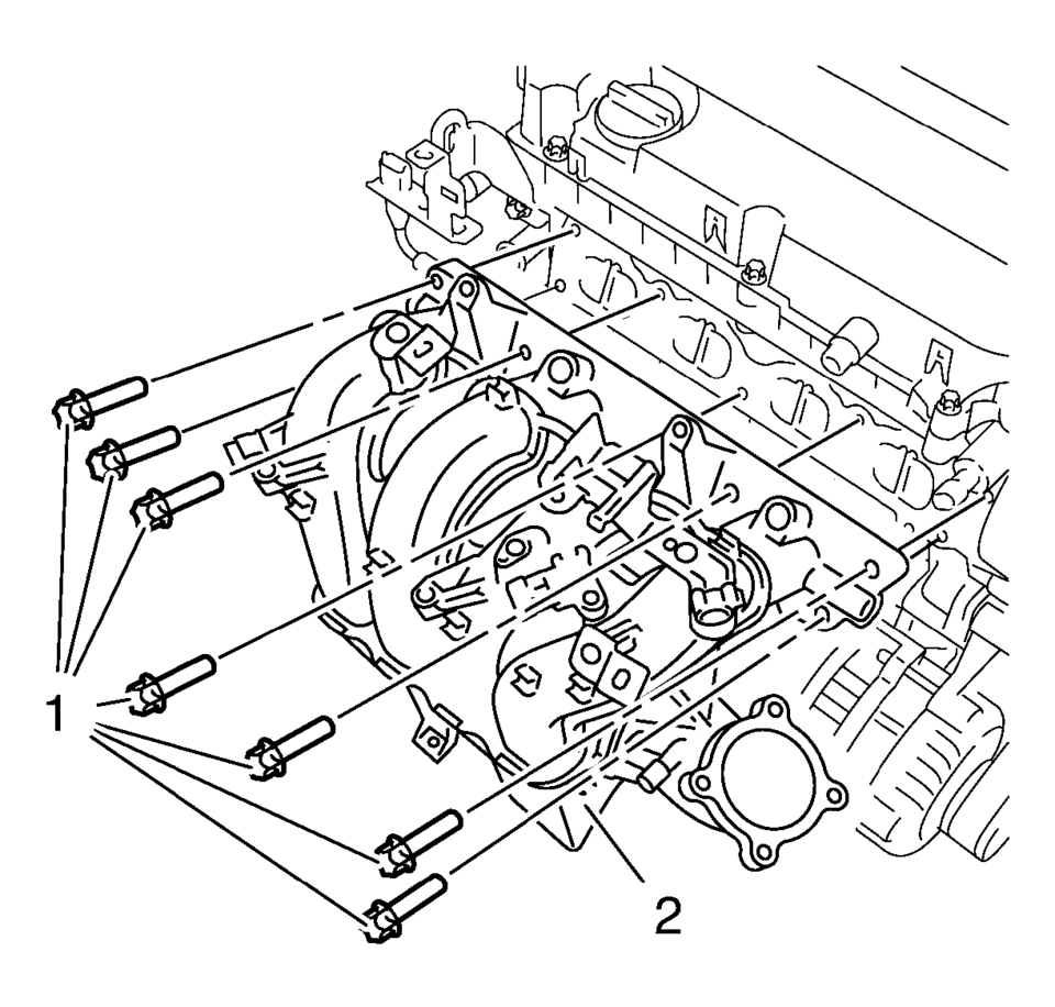
- Remove the intake manifold bolts (1) intake manifold (2).
- Remove engine coolant thermostat housing. Refer to Engine Coolant Thermostat Housing Replacement.
- Remove the 2 camshaft position actuator solenoid valve. Refer Camshaft Position Actuator Solenoid Valve Replacement.
- Remove the 2 camshaft position sensor. Refer to Camshaft Position Sensor Replacement.
- Clean and inspect the cylinder head. Refer to Cylinder Head Cleaning and Inspection.
- For disassembly of the cylinder head, refer to Cylinder Head Disassemble.
- Installation Procedure
-
- For assembly of the cylinder head, refer to Cylinder Head Assemble.
- Clean sealing surfaces of engine front cover and engine block from grease and old gasket material.
- Install the 2 camshaft position sensor. Refer to Camshaft Position Sensor Replacement.
- Install the 2 camshaft position actuator solenoid valve. Refer Camshaft Position Actuator Solenoid Valve Replacement.
- Install engine coolant thermostat housing. Refer to Engine Coolant Thermostat Housing Replacement.
- Install the intake manifold (2) and the intake manifold bolts (1) and
tighten to 20 Y (15 lb ft)
.
- Install the cylinder head (2) with the NEW gasket and hand start the NEW bolts.
- Tighten the bolts (1) in 5 passes. Use the EN-45059 sensor kit :
Caution:
Refer to Fastener Caution.
Note:
Note the correct tightening sequence.
- First pass to 25 Y (18 lb ft).
- Second pass to 90°.
- Third pass to 90°.
- Fourth pass to 90°.
- Final pass to 45°.
- Install engine support fixture. Refer to Engine Support Fixture.
- Remove the floor jack from the vehicle.
- Install the exhaust manifold. Refer to Exhaust Manifold with Catalytic Converter Replacement.
- Install the timing belt rear cover (1) and tighten to 6 Y (53.1 lb in)
.
- Install the camshaft sprocket intake (1) and exhaust (2). Refer to Camshaft Sprocket Replacement.
- Install the timing belt (1). Refer to Timing Belt Replacement.
- Install the timing belt tensioner bolt (1) and the timing belt tensioner (2). Refer to Timing Belt Tensioner Replacement.
- Install the timing belt lower front cover (1). Refer to Timing Belt Lower Front Cover Replacement.
- Install the crankshaft balancer (2). Refer to Crankshaft Balancer Replacement.
- Install the timing belt center front cover. Refer to Timing Belt Center Front Cover Replacement.
- Install the upper timing cover (1). Refer to Timing Belt Upper Front Cover Replacement.
- Install the engine mount bracket (1). Refer to Engine Mount Bracket Replacement.
- Install the drive belt (1). Refer to Drive Belt Replacement.
- Install the engine mount. Refer to Engine Mount Replacement.
- Remove engine support fixture. Refer to Engine Support Fixture.
- Install the camshaft cover (1). Refer to Camshaft Cover Replacement.
- Connect PCV hose. Refer to Positive Crankcase Ventilation Hose/Pipe/Tube Replacement.
- Install the ignition coil (2) . Refer to Ignition Coil Replacement.
- Connect the throttle body heater inlet pipe (1).
ii
- Install the inlet hose (2) and outlet (3) to the engine.
- Install the inlet and outlet heater hose clamp (1) at the engine using BO-38185 pliers.
- Install the radiator inlet hose (2) to the engine.
- Install the radiator inlet hose clamp (1) at the engine using BO-38185 pliers.
- Install the coolant surge tank. Refer to Radiator Surge Tank Replacement.
- Connect the fuel feed pipe. Refer to Fuel Feed Pipe Replacement.
- Connect EVAP purge solenoid pipes from solenoid. Refer to Evaporative Emission System Hose/Pipe Replacement.
- Fill the cooling system. Refer to Cooling System Draining and Filling.
- Connect the negative battery cable. Refer to Battery Negative Cable Disconnection and Connection.
- Check and correct the engine oil.
 Cylinder Head Removal
Loosen the 12 cylinder head bolts in the sequence as shown. Use the following
procedure:
Loosen the cylinder head bolts 90 degrees.
Loosen the cylinder head bolts 180& ...
 Engine Mounts
...
Other materials:
Towing the Vehicle
Notice: Incorrectly towing a disabled vehicle may cause damage. The
damage would not be covered by the vehicle warranty. Do not lash or hook to
the chassis components including the front and rear subframes, suspension control
arms and links during towing and recovery of a disabled vehicl ...
Door Lock and Ignition Lock Folding Key Blade Removal and Installation
Special Tools
BO-51098 Flip Key Blade Fixture
For equivalent region tools, refer to Special Tools.
Caution: Failure to properly support the Remote Keyless Entry
(RKE) transmitter assembly while replacing the key blade may cause internal
damage to the transmitter assembly. ...
Clutch and Differential Housing Assemble
Special Tools
R-0007761 Universal Handle for Pullers and Installers
R-0407009 Countershaft Front Bearing Driver
R-0407010 Input Shaft Needle Bearing Puller and Driver
R-0407014 Gearshift Device Bushing Driver ?#8201;Use with R-0007761
S-9707500 Axle Shaft Seal Installer
For ...

0.0065