Chevrolet Sonic Repair Manual: Drive Range, First Gear (Gen 2)
As the vehicle speed increases, the transmission control module (TCM) receives input signals from the automatic transmission input and output speed sensors, throttle position sensor and other vehicle sensors to determine the precise moment to de-energize or ?urn OFF?the shift solenoid, and to command OFF the normally-high R1/456 pressure control solenoid.
- Low & Reverse Clutch Releases
-
Shift Solenoid
The shift solenoid is commanded OFF allowing shift solenoid fluid pressure to exhaust from the clutch select valve, the default override valve, and the TCC regulator apply valve.
Clutch Select Valve
Shift solenoid fluid is exhausted from the clutch select valve and clutch select valve spring force moves the valve to the released position. This allows R1 fluid pressure to pass through the valve into the exhaust backfill circuit. Drive fluid from the manual valve passes through the clutch select valve and enters the drive 1-6 fluid circuit. Drive 1-6 fluid is routed to the R1/4-5-6 clutch regulator valve, the 3-5-reverse clutch regulator valve, and the TCC regulator apply valve.
Low and Reverse Clutch
Low and reverse clutch spring force moves the low and reverse clutch piston to release the low and reverse clutch plates and force R1 fluid to exhaust from the case assembly. The exhausting R1 fluid is routed to the clutch select valve where it enters the exhaust backfill circuit.
- Fluid Pressure Directed in Preparation for a Shift
-
R1/456 Pressure Control (PC) Solenoid
The R1/456 PC solenoid is commanded OFF allowing PCS R1/456 clutch fluid to exhaust from the R1/4-5-6 clutch regulator valve and the R1/4-5-6 clutch boost valve.
R1/4-5-6 Clutch Regulator Valve
R1/4-5-6 clutch regulator valve spring force moves the valve to the released position, allowing R1/456 clutch feed fluid to enter the exhaust backfill circuit, and drive 1-6 fluid to enter the latch fluid circuit. Latch fluid is routed to the #1 ball check valve.
#1 Ball Check Valve
Latch fluid pressure seats the #1 ball check valve against the 456 clutch fluid circuit. Latch fluid is then directed to the clutch select valve. Latch fluid combines with clutch select valve spring force and holds the valve in this position during all six forward gear ranges.
#2 Ball Check Valve
Drive 1-6 fluid pressure seats the #2 ball check valve against the 35 reverse clutch feed fluid passage, and is directed into the 35 reverse clutch feed/drive 1-6 circuit. 35 reverse clutch feed/drive 1-6 fluid is routed to the #3 ball check valve.
#3 Ball Check Valve
35 reverse clutch feed/drive 1-6 fluid pressure unseats the #3 ball check valve and is directed to the 3-5-reverse clutch regulator valve.
- Fluid Pressure Directed in Preparation for Torque Converter Clutch (TCC) Apply
-
TCC Regulator Apply Valve
Drive 1-6 fluid is routed to the TCC regulator apply valve in preparation for TCC apply.
- Drive Range, First Gear ?#8201;Gen 2/Hybrid
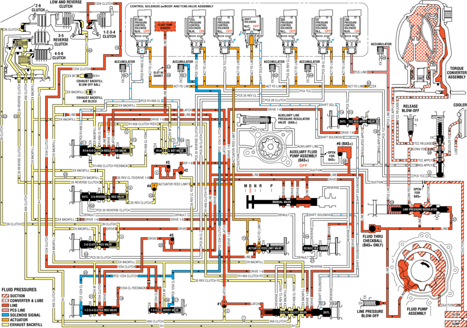
solenl1ld(wlbijdv valve assembly ms n.h. off off clutch clutch tdrdue converter assemnlv exhaust ex exnaust backfill pcs ex backf release cddleh at blow-off ex badkhll: pressure valve :1: iii line (sh clutch feedback off ex ii sucnuu lwe h_ .:. reverse clutch sun ree 35 rev clutch res reverse clutch default sulenoid :ex -drive drive fluid mu ehedkball pcs 2e _default ex reverse id fluid pnessunes sucnou converter lube lime valve line pressure solenoid signal 1_ clutch clutch :i exhaust backfill ,, ,,
 Drive Range, First Gear (Gen 1)
As the vehicle speed increases, the transmission control module (TCM) receives
input signals from the automatic transmission input and output speed sensors, throttle
position sensor and other vehi ...
 Drive Range, First Gear Engine Braking (Gen 1)
When the gear selector lever is moved to the Drive (D) range from the Neutral
(N) position, the transmission will provide engine braking. In this operating range,
the normally-low 1234 pressure co ...
Other materials:
Engine Oil Cooler Inlet Pipe Replacement (LUW)
Removal Procedure
Drain the cooling system. Refer to Cooling System Draining and Filling.
Remove the exhaust manifold with catalytic converter. Refer to Exhaust
Manifold with Catalytic Converter Replacement.
Remove the engine oil cooler pipe bolts (1) an ...
Transmission Mount Bracket Replacement - Rear
Removal Procedure
Raise and support the vehicle. Refer to
Lifting and Jacking the Vehicle.
Remove the front suspension skid plate, if equipped.
Refer to Drivetrain and Front Suspension Frame Skid
Plate Replacement.
Using a suitable jack stand, support the rear of the ...
The second generation of the Mitsubishi Outlander Review (2007-2013)
Mitsubishi's collaboration with the French group PSA (Peugeot-Citroen) in Europe
and the adoption of a Volkswagen diesel engine marked significant milestones in
the development of the second-generation Outlander.
After a successful five-year run, Mitsubishi bid farewell to the first-genera ...

0.0071