Chevrolet Sonic Repair Manual: Drive Range - Fourth Gear (Gen 1)
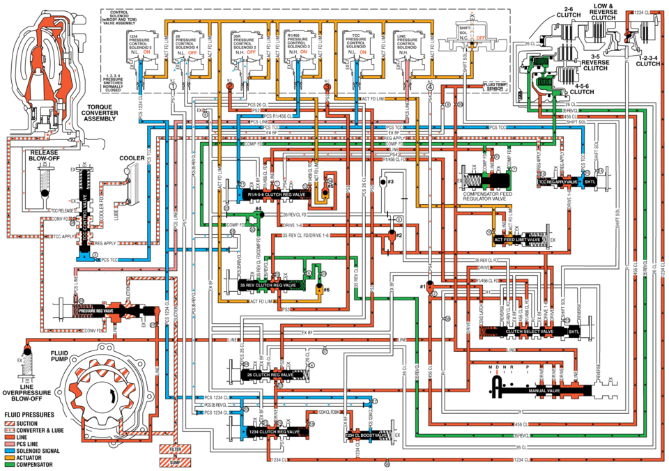
As vehicle speed increases, the transmission control module (TCM) processes input signals from the automatic transmission input and output speed sensors, the throttle position sensor and other vehicle sensors to determine the precise moment to command OFF the normally-high 35R pressure control solenoid 2. At the same time, the normally-low R1/456 pressure control solenoid 3 is commanded ON to regulate 4-5-6 clutch apply and the transmission shifts into Fourth gear.
- 4-5-6 Clutch Applies
-
R1/456 Pressure Control (PC) Solenoid 3
The R1/456 PC solenoid 3 is commanded ON allowing actuator feed limit fluid to enter the PCS R1/456 clutch fluid circuit. PCS R1/456 clutch fluid is routed through orifice #11 to the R1/456 clutch regulator valve.
R1/4-5-6 Clutch Regulator Valve
PCS R1/456 clutch fluid, at the R1/4-5-6 clutch regulator valve, opposes R1/4-5-6 clutch regulator valve spring force and orificed R1/456 clutch feed fluid pressure to regulate line pressure into the R1/456 clutch feed circuit. R1/456 clutch feed fluid is then routed to the clutch select valve, through orifice #12 to the spring end of the R1/4-5-6 clutch regulator valve, and through orifice #34 to ball check valve #5. When the R1/4-5-6 clutch regulator valve is in this position, PS4 fluid exhausts through the valve allowing the normally-closed #4 pressure switch to close.
Clutch Select Valve
R1/456 clutch feed fluid passes through the clutch select valve and enters the 456 clutch circuit. 456 clutch fluid is routed to the 4-5-6 clutch assembly, and through orifice #2 to the #1 ball check valve.
#1 Ball Check Valve
Orificed 456 clutch fluid pressure seats the #1 ball check valve against the exhausting PS4 fluid passage. 456 clutch fluid is then directed into the CSV2 latch circuit to replace the exhausting PS4 pressure and is routed to the clutch select valve. CSV2 latch fluid combines with clutch select valve spring force and holds the valve in this position during all six forward gear ranges.
4-5-6 Clutch
456 clutch fluid enters the 3-5-reverse and 4-5-6 clutch housing assembly, and moves the 4-5-6 clutch piston against spring force and compensator feed pressure to apply the 4- 5-6 clutch plates.
#5 Ball Check Valve
R1/456 clutch feed fluid unseats the #5 ball check valve, allowing excess pressure to pass into the actuator feed limit circuit. This helps to control clutch apply fluid pressure and clutch apply feel.
- 3-5-Reverse Clutch Releases
-
35R Pressure Control (PC) Solenoid 2
The 35R PC solenoid 2 is commanded OFF allowing PCS 35 reverse clutch fluid from the 3-5-reverse clutch regulator valve to exhaust.
3-5-Reverse Clutch Regulator Valve
PCS 35 reverse clutch fluid exhausts, allowing 3-5-reverse clutch regulator valve spring force to move the 3-5-reverse clutch regulator valve to the released position. This allows 35 reverse clutch fluid pressure to exhaust into the compensator feed circuit in order to assist the 3-5-reverse clutch piston spring to quickly release the 3-5-reverse clutch. With the 3-5-reverse clutch regulator valve in this position, orificed (#25) 35 reverse clutch feed/drive 1-6 fluid passes through the valve into the PS3 circuit. PS3 fluid is routed to the normally-closed #3 pressure switch and opens the switch.
3-5-Reverse Clutch
3-5-reverse clutch spring force, assisted by compensator feed pressure, moves the 3-5-reverse clutch piston to release the 3-5-reverse clutch plates and force 35 reverse clutch fluid to exhaust from the 3-5-reverse and 4-5-6 clutch housing assembly. The exhausting 35 reverse clutch fluid pressure is routed to the 3-5-reverse clutch regulator valve where it enters the 35 reverse clutch feed/compensator feed circuit.
- Torque Converter Clutch (TCC) Applies
-
Torque Converter Clutch (TCC) Pressure Control (PC) Solenoid
The TCC PC solenoid is commanded ON, allowing actuator feed limit fluid to enter the PCS TCC fluid circuit. PCS TCC fluid is routed through orifice #15 to the TCC regulator apply valve and through orifice #3 to the TCC control valve.
TCC Regulator Apply Valve
PCS TCC fluid, at the TCC regulator apply valve, opposes TCC regulator apply valve spring force and orificed regulated apply fluid pressure to regulate drive 1-6 fluid into the regulated apply circuit. Regulated apply fluid is routed to the TCC control valve and through orifice #16 to the spring end of the TCC regulator apply valve.
TCC Control Valve
PCS TCC fluid moves the TCC control valve against TCC control valve spring force, allowing regulated apply fluid to pass through the valve into the TCC apply fluid circuit and apply the torque converter clutch. Converter feed fluid passes through orifice #28 to the TCC control valve, replacing TCC apply fluid, to supply the cooler feed circuit. TCC release fluid passes through the TCC control valve and is exhausted.
- Drive Range, Fourth Gear
low reverse clutch smzuom of nl on solemon __ h. solencm4 off clutch id in tohoue assembly :xixi: compensator feed drne cl ovefipfiessufie blow-off fluid pressures suction converter lube line pcs line solenoid actuator compensatdr
 Differential Carrier Removal (6T40/45/50)
Differential Carrier Removal
Callout
Component Name
1
Front Differential Carrier Bearing Assembly
2
...
 Drive Range - Fourth Gear (Gen 2)
As vehicle speed increases, the transmission control module (TCM) processes input
signals from the automatic transmission input and output speed sensors, the throttle
position sensor and other veh ...
Other materials:
Headlining Trim Panel Replacement (Sedan without Sunroof)
Headlining Trim Panel Replacement
Callout
Component Name
Warning: Do not attempt to repair or alter the head impact
energy-absorbing material glued to the headliner or to the garnish trims.
If the material is damaged ...
Front Brake Shield Replacement
Removal Procedure
Warning: Refer to Brake Dust Warning.
Raise and support the vehicle. Refer to Lifting and Jacking the Vehicle.
Remove the front tire and wheel assembly. Refer to Tire and Wheel Removal
and Installation.
Remove the front brake rotor. Refer to ...
Engine Coolant Thermostat Replacement (LUW)
Removal Procedure
Warning: Refer to Battery Disconnect Warning.
Disconnect the battery negative cable. Refer to Battery Negative Cable
Disconnection and Connection.
Drain the coolant. Refer to Cooling System Draining and Filling.
Disconnect the en ...

0.0065