Chevrolet Sonic Repair Manual: Drum Brake Adjustment
Special Tools
CH-21177-A Drum to Brake Shoe Clearance Gauge
For equivalent regional tools, refer to Special Tools.
- Ensure the park brake lever is in the fully released position.
- Remove the front floor console cupholder insert.
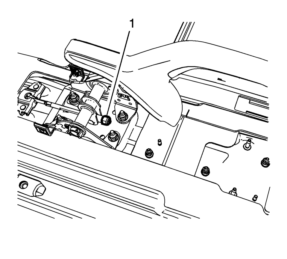
- Using ONLY HAND TOOLS, loosen the adjusting nut (1) completely to the end of the front cable threaded rod.
- Raise and support the vehicle. Refer to Lifting and Jacking the Vehicle.
- Remove the rear tire and wheel assemblies. Refer to Tire and Wheel Removal and Installation.
- Remove the brake drums. Refer to Brake Drum Replacement.
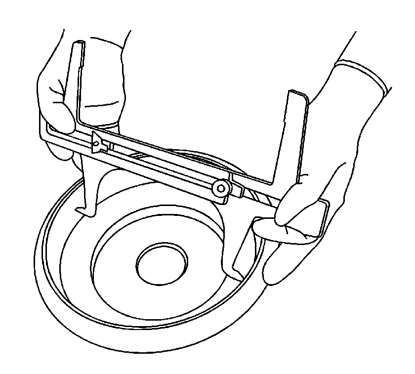
- Position the CH-21177-A Drum to Brake Shoe Clearance Gauge to the widest point of the brake drum inside diameter.
- Firmly hand tighten the set screw on the CH-21177-A Drum to Brake Shoe Clearance Gauge .
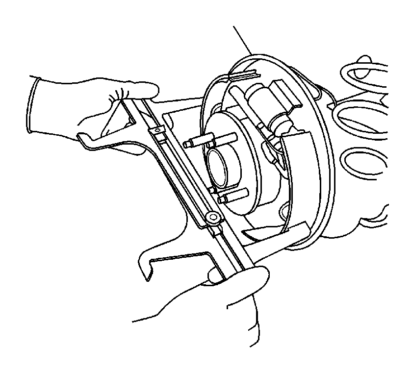
- Remove the CH-21177-A Drum to Brake Shoe Clearance Gauge from the brake drum and position it over the corresponding brake shoe assembly at its widest point.
- While holding the CH-21177-A Drum to Brake Shoe Clearance Gauge in position, insert a proper feeler gauge between one side of the CH-21177-A Drum to Brake Shoe Clearance Gauge , and the corresponding brake shoe lining.
- Rotate the brake shoe adjuster screw until the brake shoe linings contact the CH-21177-A Drum to Brake Shoe Clearance Gauge and the feeler gauge. Refer to Drum Brake Component Specifications.
- Repeat the above steps for the opposite brake drum and brake shoe assembly.
- Install the brake drums. Refer to Brake Drum Replacement.
- Adjust the park brake. Refer to Parking Brake Adjustment.
- Install the rear tire and wheel assemblies. Refer to Tire and Wheel Removal and Installation.
- Lower the vehicle.
- Install the front floor console cupholder insert.
Warning:
Refer to Brake Dust Warning.
Note:
Use ONLY HAND TOOLS when loosening or tightening the adjusting nut.
 Drum Brake Adjusting Hardware Replacement (J93, J94)
Removal Procedure
Warning: Refer to Brake Dust Warning.
Raise and support the vehicle. Refer to Lifting and Jacking the Vehicle.
Remove the tire and wheel assembly. Re ...
 Drum Brake Hardware Inspection
Warning: Refer to Brake Dust Warning.
Visually inspect the drum brake upper return spring (1) for the following
conditions:
Excessive corrosion
Excessive stretchin ...
Other materials:
Body Hinge Pillar Lower Reinforcement Replacement
Removal Procedure
Warning: Refer to Approved Equipment for Collision Repair
Warning.
Disable the SIR system. Refer to SIR Disabling and Enabling.
Disconnect the negative battery cable. Refer to Battery Negative Cable
Disconnection and Connection.
Remove all ...
Front Differential Carrier Installation (6T30)
Front Differential Carrier Installation
Callout
Component Name
1
Final Drive Sun Gear
2
Differential Carrier Assembly
...
Differential Case Disassemble
Special Tools
6-9607346 Sensor Ring Gear Puller
J-810704 Steering Column Center Bar Puller
J-810721 Axle Shaft Seal Remover Support Base
R-0006749 Support Base
R-0407011 Bearing Race Remover
R-0007761 Universal Handle for Pullers and Installers
S-9407195 Pinion Gear Case Bearing ...

0.0062