Chevrolet Sonic Repair Manual: Drum Brake Adjusting Hardware Replacement (J93, J94)
- Removal Procedure
-
- Raise and support the vehicle. Refer to Lifting and Jacking the Vehicle.
- Remove the tire and wheel assembly. Refer to Tire and Wheel Removal and Installation.
- Remove the brake drum. Refer to Brake Drum Replacement.
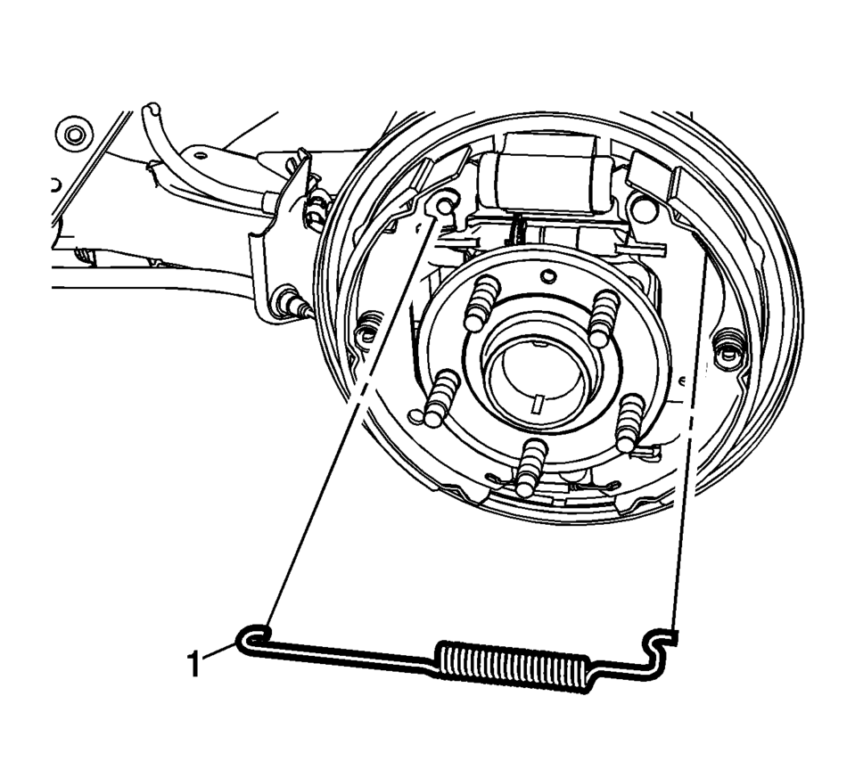
- Remove the upper brake shoe return spring (1).
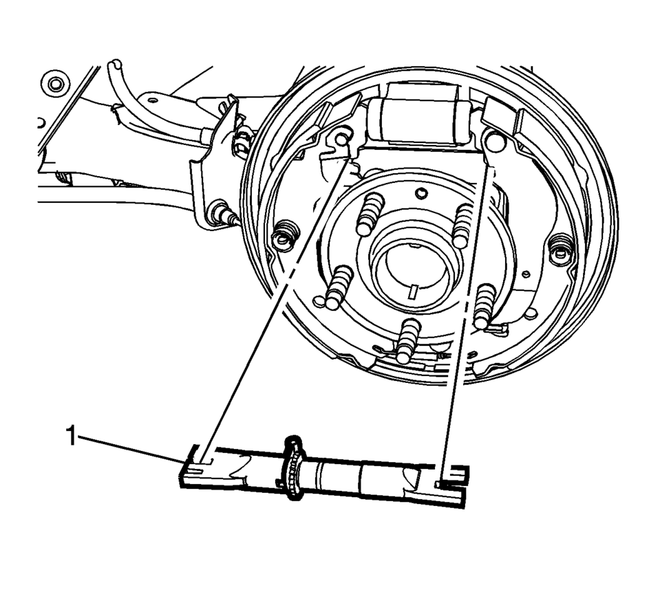
- Remove brake shoe adjuster (1).
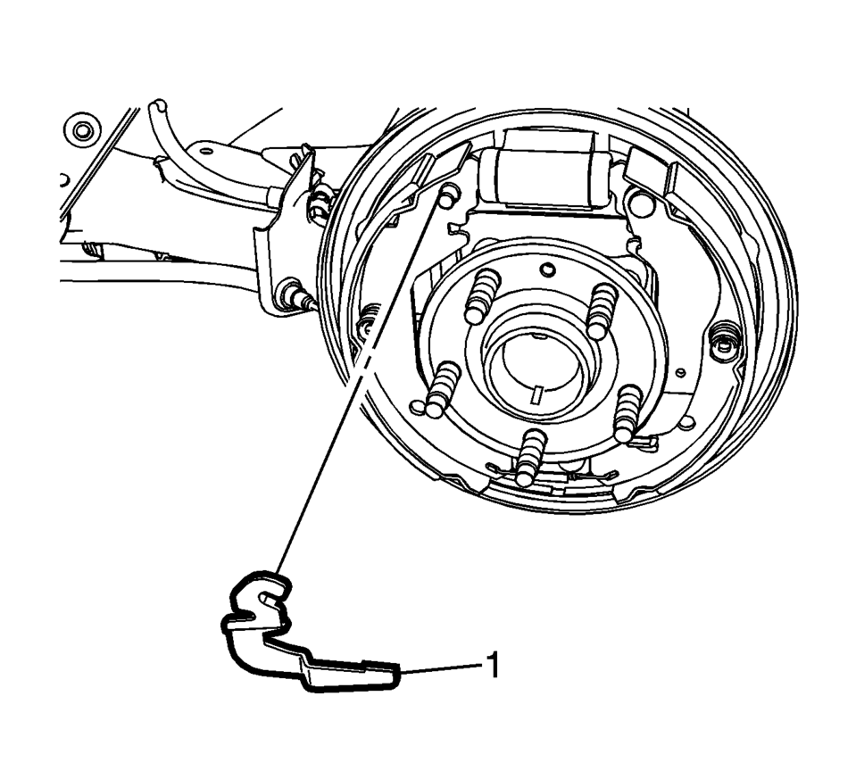
- Remove the brake shoe adjuster actuator lever (1).
- Inspect the drum brake adjusting hardware and replace any damaged components as necessary. Refer to Drum Brake Adjusting Hardware Inspection.
- Disassemble the brake shoe adjuster and thoroughly clean the adjuster screw threads of any corrosion.
- Apply a light coat of high temperature brake lubricant to the brake shoe adjuster screw threads.
Warning:
Refer to Brake Dust Warning.
- Installation Procedure
-
- Assemble the brake shoe adjuster, setting the adjuster to the fully retracted position.
- Clean the drum brake backing plate of any dirt and debris.
- Apply a light coat of high temperature brake lubricant to the brake drum backing plate shoe contact surfaces.
- Install the brake shoe adjuster actuator lever (1).
- Install brake shoe adjuster (1).
- Install the upper brake shoe return spring (1).
- Adjust the drum brakes. Refer to Drum Brake Adjustment.
- Install the brake drum. Refer to Brake Drum Replacement.
- Install the tire and wheel assembly. Refer to Tire and Wheel Removal and Installation.
 Drum Brake Adjusting Hardware Inspection
Warning: Refer to Brake Dust Warning.
Visually inspect the adjuster actuator spring (1) for the following conditions:
Excessive stretching
Excessive bending
Exces ...
 Drum Brake Adjustment
Special Tools
CH-21177-A Drum to Brake Shoe Clearance Gauge
For equivalent regional tools, refer to Special Tools.
Warning: Refer to Brake Dust Warning.
Ensure the park brake lever ...
Other materials:
Overview (Radio with CD/USB)
91011121314151617
O /VOL (Power/Volume)
Turns the system on or off and adjusts the volume.
Z (Eject)
Removes a disc from the CD slot.
Buttons 1−6
Radio: Saves and selects favorite stations.
AUX Port
3.5 mm (1/8 in) connection for external devices.
...
Immobilizer Description and Operation
The immobilizer system functions are provided by the body control module (BCM)
and the engine control module (ECM), as well as any modules which store and report
the environment identifier.
When an ignition key is inserted into the ignition lock cylinder and the ignition
is switched ON, the ...
Drivetrain and Front Suspension Frame Skid Plate Replacement
Removal Procedure
Raise and support the vehicle. Refer to Lifting and Jacking the Vehicle.
Remove the mounting bolts (1) for the front suspension frame skid plate.
Remove the front suspension frame skid plate (2).
Installation Procedure ...

0.0047