Chevrolet Sonic Repair Manual: Gear Position Sensor Replacement
|
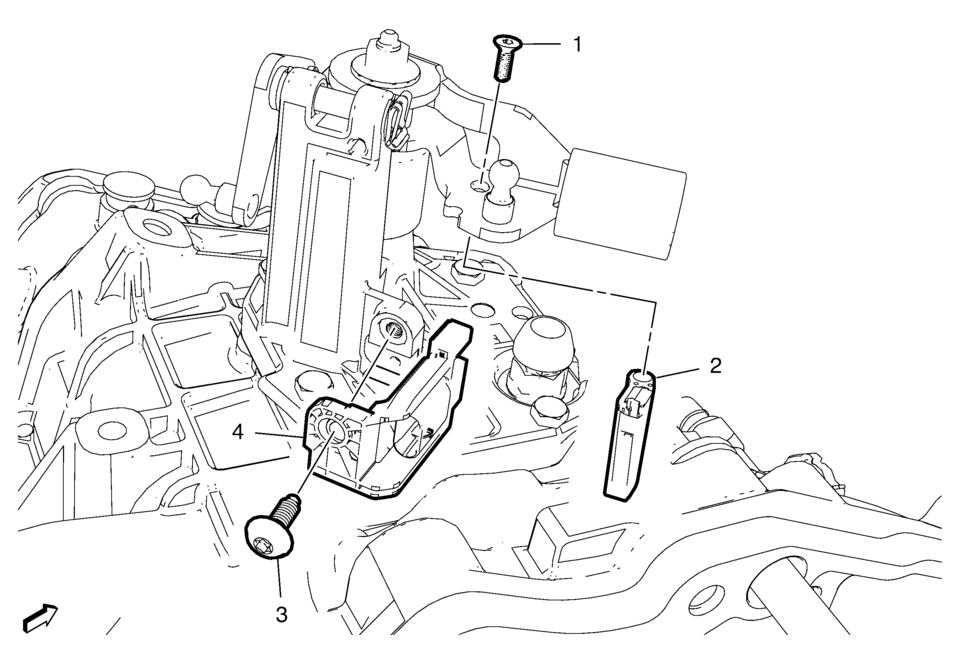
Callout |
Component Name |
|---|---|
|
Preliminary Procedure
Unclip the engine control module (ECM) and bracket from the battery tray. |
|
|
1 |
Gear Position Sensor Magnet Bolt Caution: Refer to Fastener Caution.
8 Y (71 lb ft) |
|
2 |
Gear Position Sensor Magnet |
|
3 |
Gear Position Sensor Bolt Tighten
8 Y (71 lb ft) |
|
4 |
Gear Position Sensor Procedure
|
 Automatic Transmission Shift Lock Control Function Check
Warning: When you are doing this inspection, the vehicle could move
suddenly. If the vehicle moves, you or others could be injured.
Before starting this check, be sure there is enough roo ...

Other materials:
Overview (Radio with CD/USB)
91011121314151617
O /VOL (Power/Volume)
Turns the system on or off and adjusts the volume.
Z (Eject)
Removes a disc from the CD slot.
Buttons 1−6
Radio: Saves and selects favorite stations.
AUX Port
3.5 mm (1/8 in) connection for external devices.
...
Electronic Brake Control Module Replacement
Removal Procedure
Warning: Refer to Brake Fluid Irritant Warning.
Caution: Refer to Brake Fluid Effects on Paint and Electrical
Components Caution.
Remove the battery tray. Refer to Battery Tray Replacement.
Disconnect the electronic brake control module (EBC ...
Drivetrain and Front Suspension Frame Skid Plate Replacement
Removal Procedure
Raise and support the vehicle. Refer to Lifting and Jacking the Vehicle.
Remove the mounting bolts (1) for the front suspension frame skid plate.
Remove the front suspension frame skid plate (2).
Installation Procedure ...

0.0053