Chevrolet Sonic Repair Manual: Lubrication Description
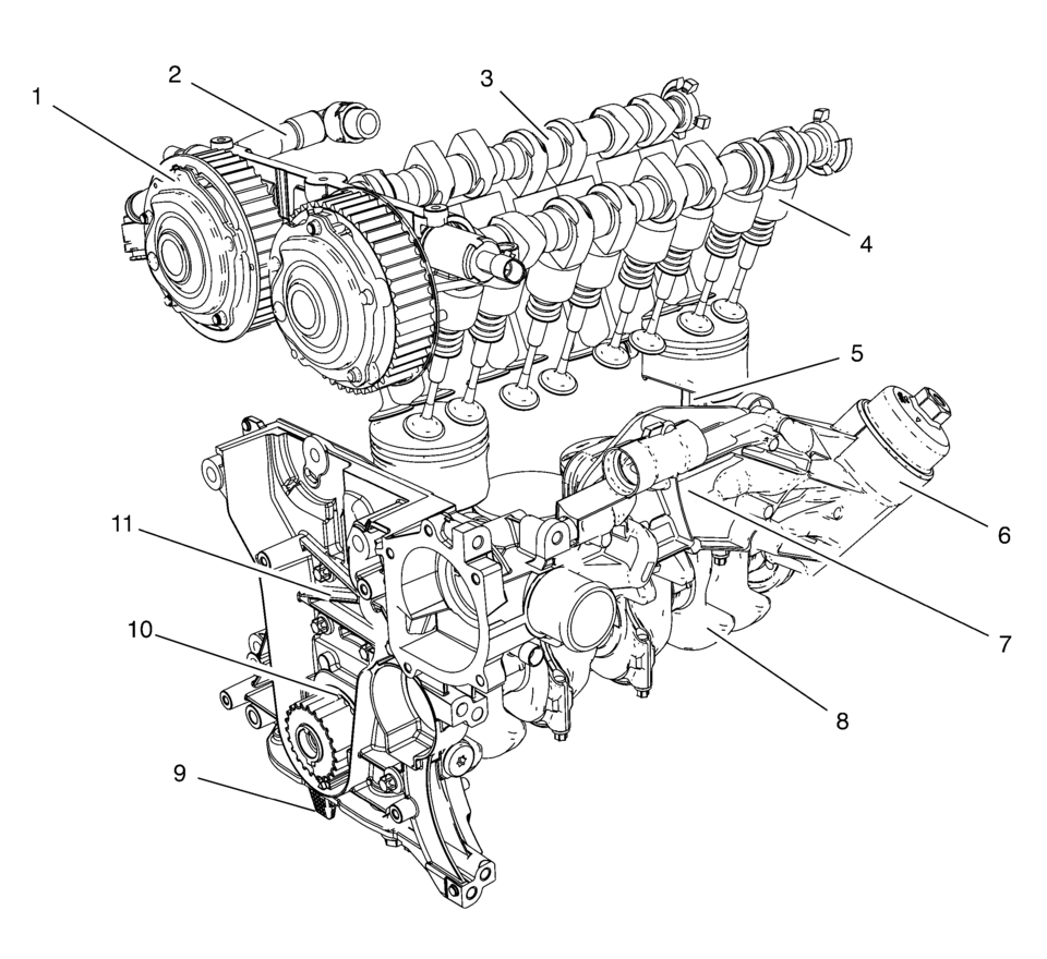
Oil is applied under pressure to the crankshaft (8), connecting rods (5), camshaft adjuster (1), camshaft bearing surfaces (3) and valve tappets (4). All other moving parts are lubricated by gravity flow or splash. Oil enters the rotor type oil pump (10) through a fixed inlet screen (9). The oil pump is driven by the crankshaft. The oil pump body is within the engine front cover (11). The pressurized oil from the pump passes through the oil cooling system and the oil filter (6). The oil filter is integrated with the oil cooling system housing (7) that is connected to the front of the engine block. The oil filter is a disposable cartridge type. A by-pass valve in the filter cap allows continuous oil flow in case the oil filter should become restricted. The connecting rod bearings are oiled by constant oil flow passages through the crankshaft connecting the main journals to the rod journals. A groove around each upper main bearing furnishes oil to the drilled crankshaft passages. The pressurized oil passes through the cylinder head restrictor orifice into the cylinder head and then into each camshaft feed gallery. An engine oil pressure switch or sensor is installed at the end. Oil returns to the oil pan through passages cast into the cylinder head. The crankcase ventilation system does not contain to the lubrication system, but to the oil circuit. It is used to consume crankcase vapors in the combustion process instead of venting them to atmosphere. Fresh air from the intake system is supplied to the crankcase, mixed with blow by gases and then passed through a calibrated orifice of the crankcase ventilation tube (2) into the intake manifold.
 Generator Replacement (LUW)
Removal Procedure
Disconnect the negative battery cable. Refer to Battery Negative Cable
Disconnection and Connection.
Raise and support the vehicle. Refer to Lifting and Jacking ...
 Neutral - Engine Running (Gen 1)
When the gear selector is moved to the Neutral (N) position, the hydraulic and
electrical system operation is identical to Park (P) range. However, if Neutral
is selected after the vehicle was ope ...
Other materials:
Cruise Control Switch Replacement
Cruise Control Switch Replacement
Callout
Component Name
Preliminary Procedure
Remove the steering wheel inflatable restraint module. Refer to
Airbag Steering Wheel Module Replacement.
1
Steer ...
Tire Dismounting and Mounting (Match Mounting)
Match mounting is required on any wheel/tire assembly not within RFV specification.
Important: If a wheel/tire assembly is not within the RFV specification
after match mounting, the tire must be returned to the tire manufacturer.
All wheel weights should be removed prior ...
Transmission Mount Bracket Replacement - Left Side
Removal Procedure
Remove the left transmission mount. Refer to
Transmission Mount Replacement - Left Side.
Remove the three left transmission mount bracket to
transmission bolts (1).
Remove the left transmission mount bracket (2) from
the transmis ...

0.006