Chevrolet Sonic Repair Manual: Generator Replacement (LUW)
- Removal Procedure
-
- Disconnect the negative battery cable. Refer to Battery Negative Cable Disconnection and Connection.
- Raise and support the vehicle. Refer to Lifting and Jacking the Vehicle.
- Remove the drive belt. Refer to Drive Belt Replacement.
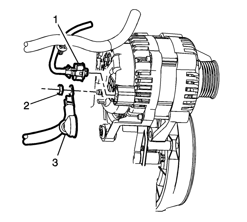
- Remove the engine harness connector (1) and the battery positive cable generator fastener (2).
- Remove the battery positive cable (3) from the back of the generator.
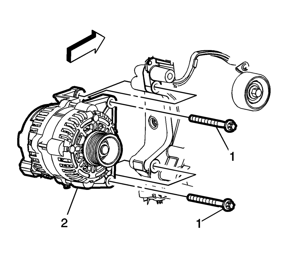
- Remove the generator mounting fasteners (1) and remove the generator (2) from the engine.
- Installation Procedure
-
- Install the generator (2) with the mounting fasteners (1) and tighten
to 35 Y (26 lb ft)
.
- Install the battery positive cable (3) and the engine harness connector (1)
to the back of the generator. Tighten fastener (2) to 9 Y (80 lb in)
.
- Install the drive belt. Refer to Drive Belt Replacement.
- Connect the negative battery cable. Refer to Battery Negative Cable Disconnection and Connection.
Caution:
Refer to Fastener Caution.
- Install the generator (2) with the mounting fasteners (1) and tighten
to 35 Y (26 lb ft)
 Generator Replacement (LUV)
Removal Procedure
Disconnect the negative battery cable. Refer to Battery Negative Cable
Disconnection and Connection.
Raise and support the vehicle. Refer to Lifting and Jacking ...
 Lubrication Description
Oil is applied under pressure to the crankshaft (8), connecting rods (5), camshaft
adjuster (1), camshaft bearing surfaces (3) and valve tappets (4). All other movi ...
Other materials:
How to Reset the Engine Oil Life System
Reset the system whenever the engine oil is changed so that the system can calculate
the next engine oil change. To reset the system:
1. Press the MENU button to show Remaining Oil Life on the display. This display
shows an estimate of the oil’s remaining useful life. If 99% is displayed, tha ...
Drivetrain and Front Suspension Frame Replacement
Special Tools
EN-45059 Angle Meter
For equivalent regional tools, refer to Special Tools.
Removal Procedure
Support the radiator and condenser from above using the upper brackets
on each side.
Raise the vehicle on a hoist. Refer to Lifting and Jacking the Vehicle.
Re ...
Engine Mount Bracket Replacement
Engine Mount Bracket Replacement
Callout
Component Name
Preliminary Procedure
Remove the engine mount. Refer to Engine Mount Replacement.
1
Engine Mount Bracket Bolt (Qty: 3)
Cau ...

0.005