
Chevrolet Sonic Repair Manual: Generator Replacement (LUV)
- Removal Procedure
-
- Disconnect the negative battery cable. Refer to Battery Negative Cable Disconnection and Connection.
- Raise and support the vehicle. Refer to Lifting and Jacking the Vehicle.
- Remove the drive belt. Refer to Drive Belt Replacement.
- Remove the drive belt tensioner. Refer to Drive Belt Tensioner Replacement.
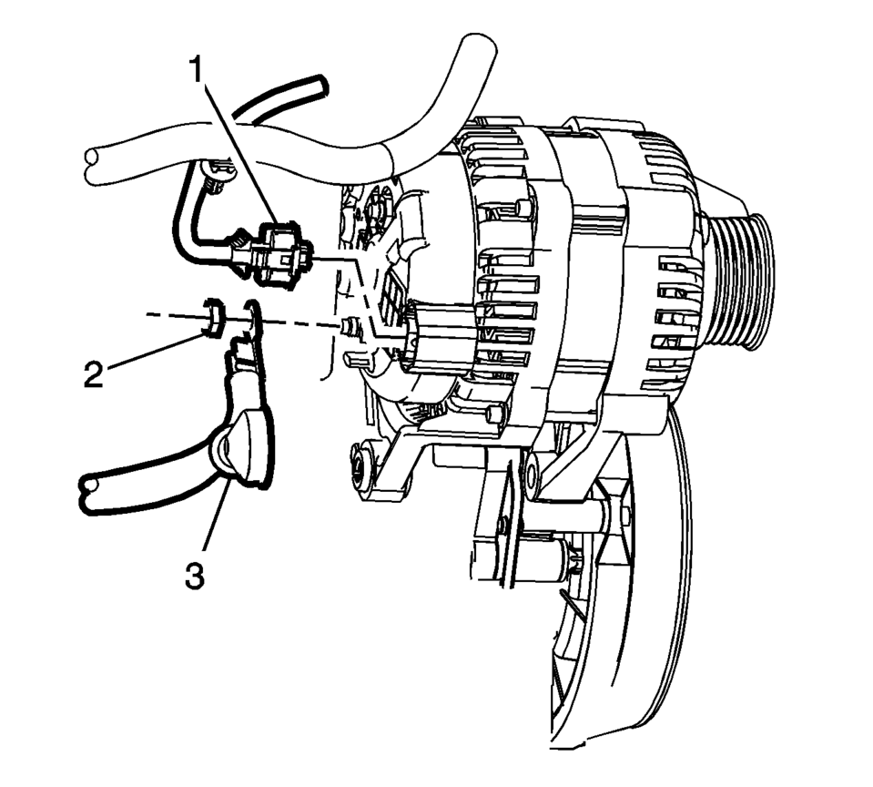
- Remove the engine harness connector (1) and the battery positive cable generator fastener (2).
- Remove the battery positive cable (3) from the back of the generator.
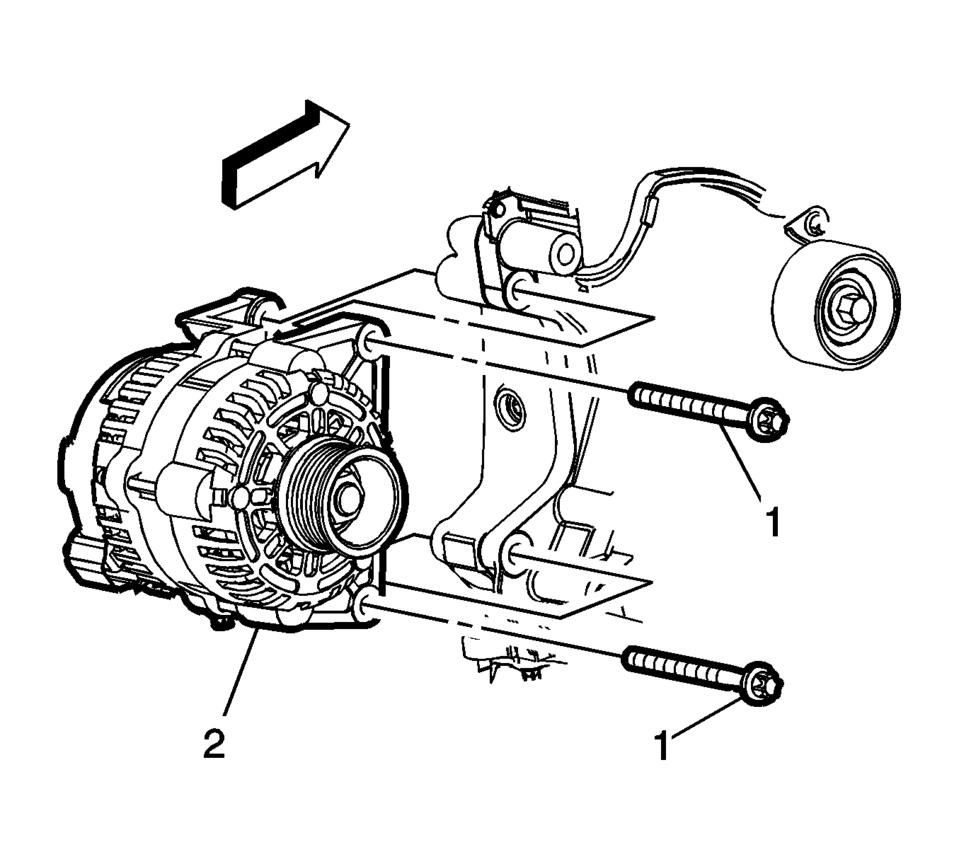
- Remove the generator mounting fasteners (1) and remove the generator (2) from the engine.
- Installation Procedure
-
- Install the generator (2) with the mounting fasteners (1) and tighten
to 35 Y (26 lb ft)
.
- Install the battery positive cable (3) and the engine harness connector (1)
to the back of the generator. Tighten fastener (2) to 9 Y (80 lb in)
.
- Install the drive belt tensioner. Refer to Drive Belt Tensioner Replacement.
- Install the drive belt. Refer to Drive Belt Replacement.
- Connect the negative battery cable. Refer to Battery Negative Cable Disconnection and Connection.
Caution:
Refer to Fastener Caution.
- Install the generator (2) with the mounting fasteners (1) and tighten
to 35 Y (26 lb ft)
 Generator Removal
Remove the 2 generator bolts (2).
Remove the generator (1).
...
 Generator Replacement (LUW)
Removal Procedure
Disconnect the negative battery cable. Refer to Battery Negative Cable
Disconnection and Connection.
Raise and support the vehicle. Refer to Lifting and Jacking ...
Other materials:
Engine Coolant Fan Replacement (LUV)
Engine Coolant Fan Replacement
Callout
Component Name
Preliminary Procedure
Remove the engine coolant fan shroud. Refer to Engine Coolant Fan Shroud
Replacement.
1
Engine Coolant Fan Motor Elect ...
Exhaust System Replacement
Removal Procedure
Special Tools
CH-6614 Chain Pipe Cutter
For equivalent regional tools, refer to Special Tools.
Warning: Refer to Protective Goggles and Glove Warning
Warning: Refer to Exhaust Service Warning.
Raise and support the vehicle. Refer to Lifting ...
Knock Sensor System Description
Circuit/System Description
The knock sensor system enables the engine control module (ECM) to control
the ignition timing for the best possible performance while protecting the engine
from potentially damaging levels of detonation. The ECM uses the knock sensor
system to test for ...

0.0059