Chevrolet Sonic Repair Manual: Steering Linkage Outer Tie Rod Inspection
Special Tools
GE-8001 Dial Indicator Set
For equivalent regional tools, refer to Special Tools.
- Inspect the outer tie rod seal. If the outer tie rod seal is torn, replace the outer tie rod. Refer to Steering Linkage Outer Tie Rod Replacement.
- Raise the side of the vehicle being inspected with a floor jack while maintaining contact between the opposite wheel and the shop floor. Support the lower control arm with a floor jack stand as far outboard as possible and remove the floor jack. Refer to Lifting and Jacking the Vehicle.
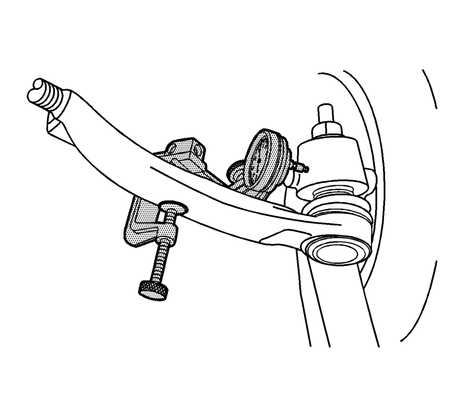
- Install the GE-8001 dial indicator between the outer tie rod and the steering knuckle as shown in the graphic. Note that the tire and wheel assembly is shown removed only for clarification of the GE-8001 dial indicator position.
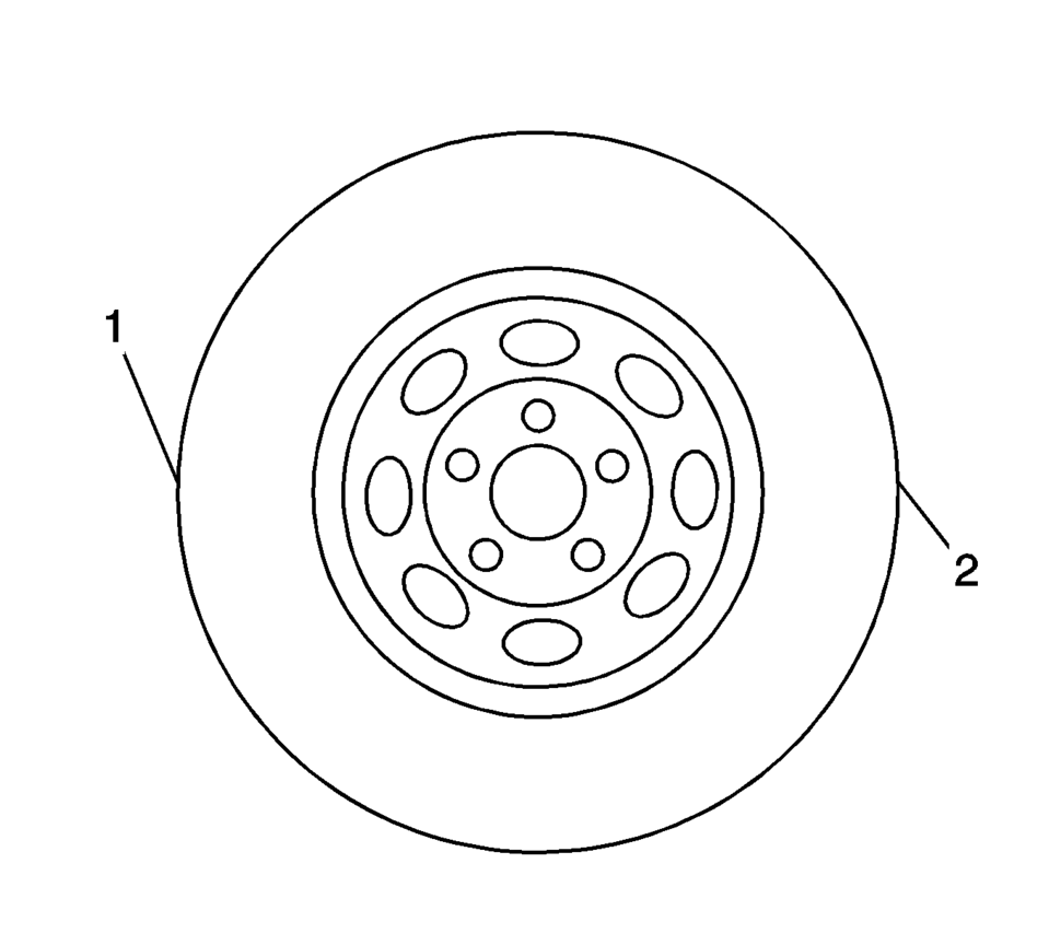
- Grasping the tire at the 3 o'clock (2) and 9 o'clock (1) positions, gently push in on one side of the tire to remove any lash.
- Zero the GE-8001 dial indicator .
- On the same side of the tire previously pushed inwards, gently pull outwards and measure the lash.
- Record the measurement shown on the GE-8001 dial indicator .
- If the measured value exceeds 0.5 mm (0.02 in), replace the outer tie rod. Refer to Steering Linkage Outer Tie Rod Replacement.
- Repeat the procedure for the other side.
Note:
This inspection procedure does not supersede local government required inspections that have more stringent requirements.
 Steering Linkage Inner Tie Rod Replacement
Steering Linkage Inner Tie Rod Replacement
Callout
Component Name
Preliminary Procedures
Raise and support the vehicle. Refer to Li ...
 Steering Linkage Outer Tie Rod Replacement
Steering Linkage Outer Tie Rod Replacement
Callout
Component Name
Preliminary Procedures
Raise and support the vehicle. Refer to Li ...
Other materials:
Mobile Telephone Microphone Replacement
Mobile Telephone Microphone Replacement
Callout
Component Name
Preliminary Procedure
Remove the dome lamp bezel. Refer to Dome Lamp
Bezel Replacement.
1
Mobile Telephone Microphone
Procedure ...
Engine Front Cover with Oil Pump Replacement
Removal Procedure
Disconnect the battery negative cable. Refer to Battery Negative Cable
Disconnection and Connection.
Set the engine to TDC. Refer to Camshaft Timing Chain Inspection.
Raise and support the vehicle. Refer to Lifting and Jacking the Vehicle.
Remove ...
Transmission Identification Information
mmmmmmmmmmm1c
The code for the M32-6 transmission will be found on the back of the transmission
housing, above the axle shaft. In addition, an Alphacode sticker will be placed
on the cover of the differential.
Transmission type (M32) (1)
Design (2)
Engine family (3) ...

0.0071