Chevrolet Sonic Repair Manual: Steering Linkage Outer Tie Rod Replacement
|
Callout |
Component Name |
|---|---|
Preliminary Procedures
|
|
|
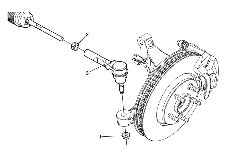
1 |
Steering Linkage Outer Tie Rod Nut Caution: Refer to Fastener Caution. Procedure
Use the EN-45059 meter in order to tighten the outer tie rod nut to the specification. Tighten
Special Tools
EN-45059 Angle Meter For equivalent regional tools, refer to Special Tools. |
|
2 |
Steering Linkage Inner Tie Rod Nut Procedure
|
|
3 |
Steering Linkage Outer Tie Rod Caution: Do not free the ball stud by using a pickle fork or a wedge-type tool. Damage to the seal or bushing may result.
Special Tools
CH-161-B Bearing Puller For equivalent regional tools, refer to Special Tools. |
 Steering Linkage Outer Tie Rod Inspection
Special Tools
GE-8001 Dial Indicator Set
For equivalent regional tools, refer to Special Tools.
Note: This inspection procedure does not supersede local government
required inspection ...

Other materials:
Front Bumper Fascia Center Support Bracket Replacement
Front Bumper Fascia Center Support Bracket Replacement
Callout
Component Name
Preliminary Procedure
Remove the front bumper fascia. Refer to Front Bumper Fascia Replacement.
1
Front Bumper Fascia ...
Floor Air Outlet Duct Replacement - Left Side (LHD)
Floor Air Outlet Duct Replacement - Left Side
Callout
Component Name
Preliminary Procedure
Remove the instrument panel insulator, if equipped.
Remove the instrument panel lower trim pad cover. Refer to Instrument
Panel Low ...
LDW system operation
The Nissan Armada LDW and I-LI systems utilize a forward-facing camera mounted
behind the windshield to continuously monitor lane markings and road boundaries.
Example
I-LI ON indicator (displayed in the vehicle information screen)
LDW/I-LI alert indicator (vehicle information displ ...

0.0066