Chevrolet Sonic Repair Manual: Steering Linkage Outer Tie Rod Inspection
Special Tools
GE-8001 Dial Indicator Set
For equivalent regional tools, refer to Special Tools.
- Inspect the outer tie rod seal. If the outer tie rod seal is torn, replace the outer tie rod. Refer to Steering Linkage Outer Tie Rod Replacement.
- Raise the side of the vehicle being inspected with a floor jack while maintaining contact between the opposite wheel and the shop floor. Support the lower control arm with a floor jack stand as far outboard as possible and remove the floor jack. Refer to Lifting and Jacking the Vehicle.
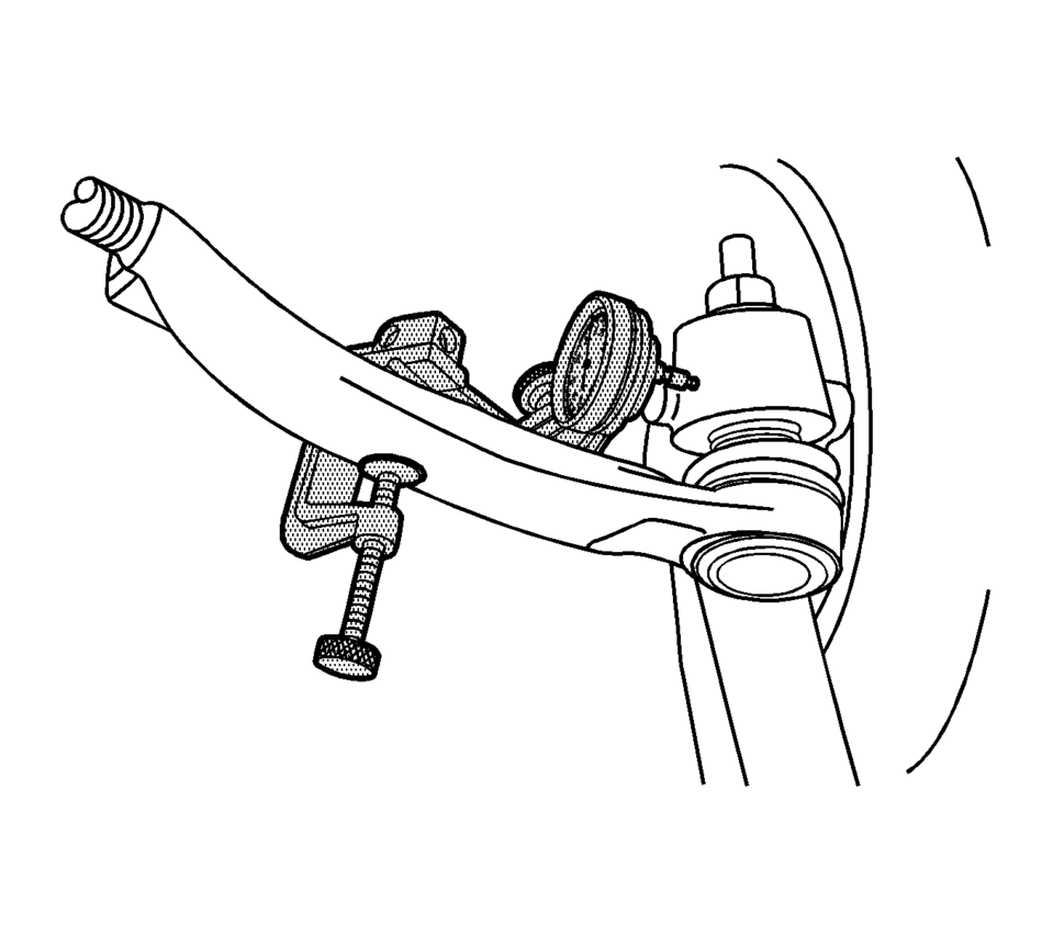
- Install the GE-8001 dial indicator between the outer tie rod and the steering knuckle as shown in the graphic. Note that the tire and wheel assembly is shown removed only for clarification of the GE-8001 dial indicator position.
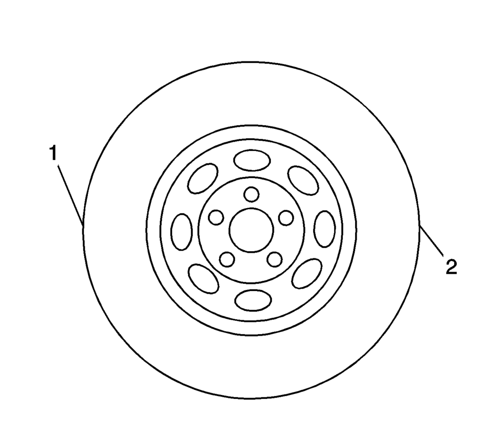
- Grasping the tire at the 3 o'clock (2) and 9 o'clock (1) positions, gently push in on one side of the tire to remove any lash.
- Zero the GE-8001 dial indicator .
- On the same side of the tire previously pushed inwards, gently pull outwards and measure the lash.
- Record the measurement shown on the GE-8001 dial indicator .
- If the measured value exceeds 0.5 mm (0.02 in), replace the outer tie rod. Refer to Steering Linkage Outer Tie Rod Replacement.
- Repeat the procedure for the other side.
Note:
This inspection procedure does not supersede local government required inspections that have more stringent requirements.
 Steering Linkage Inner Tie Rod Replacement
Steering Linkage Inner Tie Rod Replacement
Callout
Component Name
Preliminary Procedures
Raise and support the vehicle. Refer to Li ...
 Steering Linkage Outer Tie Rod Replacement
Steering Linkage Outer Tie Rod Replacement
Callout
Component Name
Preliminary Procedures
Raise and support the vehicle. Refer to Li ...
Other materials:
Tires
Every new GM vehicle has high-quality tires made by a leading tire manufacturer.
See the warranty manual for information regarding the tire warranty and where to
get service. For additional information refer to the tire manufacturer.
Warning
. Poorly maintained and improperly used tires are ...
Special Tools
Illustration
Tool Number/Description
BO-49385
BO-6626
KM-6626
S0201912
Wiper Arm Puller
...
Basic information
Example
The vehicle information display in the Nissan Armada is centrally positioned
within the instrument cluster and serves as a key interface for driver information
and system notifications. It provides real-time data and customizable settings for
enhanced driving awareness.
The Nissa ...

0.0064