Chevrolet Sonic Repair Manual: Steering Linkage Inner Tie Rod Replacement
|
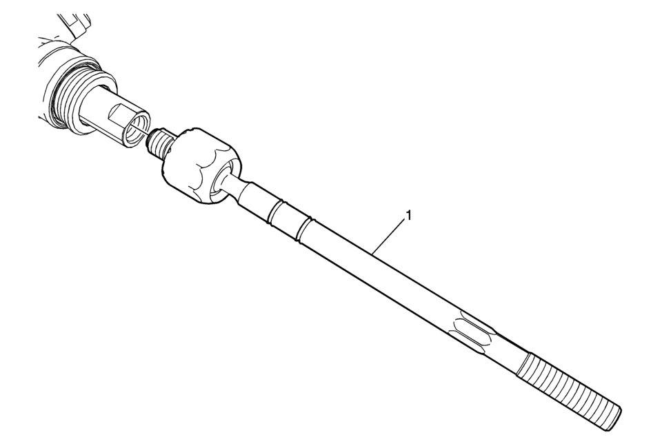
Callout |
Component Name |
|---|---|
Preliminary Procedures
|
|
|
1 |
Steering Linkage Inner Tie Rod Caution: Do not change the steering gear preload adjustment before moving the inner tie rod from the steering gear. Changing the steering gear preload adjustment before moving the inner tie rod could result in damage to the pinion and the steering gear. Caution: Refer to Fastener Caution.
100 Y (74 lb ft) |
 Steering Linkage Inner Tie Rod Inspection
Special Tools
GE-8001 Dial Indicator Set
For equivalent regional tools, refer to Special Tools.
Note: This inspection procedure does not supersede local government
required inspection ...
 Steering Linkage Outer Tie Rod Inspection
Special Tools
GE-8001 Dial Indicator Set
For equivalent regional tools, refer to Special Tools.
Note: This inspection procedure does not supersede local government
required inspection ...
Other materials:
Programming Transmitters to the Vehicle
Only RKE transmitters programmed to this vehicle will work. If a transmitter
is lost or stolen, a replacement can be purchased and programmed through your dealer.
When the replacement transmitter is programmed to this vehicle, all remaining transmitters
must also be reprogrammed. Any lost or s ...
Interior Glass
To clean, use a terry cloth fabric dampened with water. Wipe droplets left behind
with a clean dry cloth. Commercial glass cleaners may be used, if necessary, after
cleaning the interior glass with plain water.
Caution
To prevent scratching, never use abrasive cleaners on automotive glass. Abr ...
Tire Pressure Indicator Sensor Learn
Special Tools
EL-46079 Tire Pressure Monitor Diagnostic Tool
EL-50448 Tire Pressure Monitor Sensor Activation Tool
For equivalent regional tools, refer to Special Tools.
Learn Mode Description
The tire pressure monitor system uses the instrument cluster, body control
module (B ...

0.005