Chevrolet Sonic Repair Manual: Timing Belt Adjustment
Special Tools
- EN-652 Flywheel Holder
- EN-6333 Locking Pin
- EN-6340 Locking Tool
- EN-6628-A Locking Tool
- EN-45059 Torque Angle Sensor Kit
For equivalent regional tool, refer to Special Tools.
- Removal Procedure
-
- Remove the timing belt upper front cover. Refer to Timing Belt Upper Front Cover Removal.
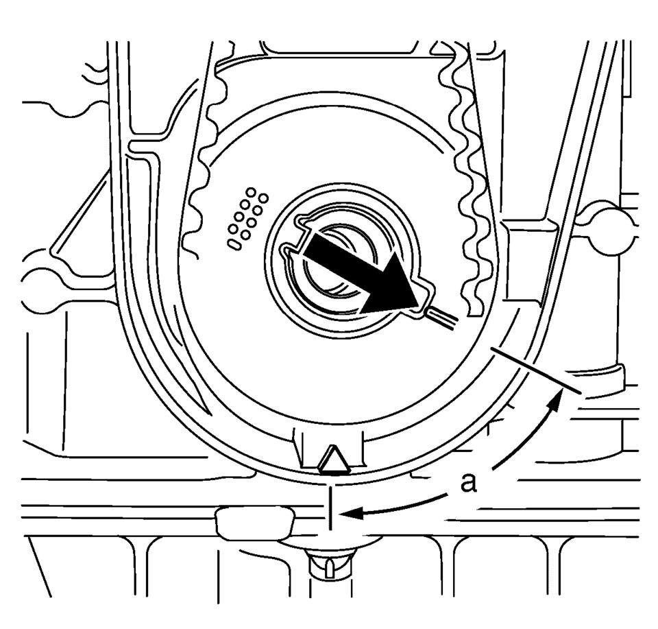
- Set the crankshaft balancer in the direction of the engine rotation to "1st cylinder TDC" (mark 1).
- Remove the camshaft cover. Refer to Camshaft Cover Removal.
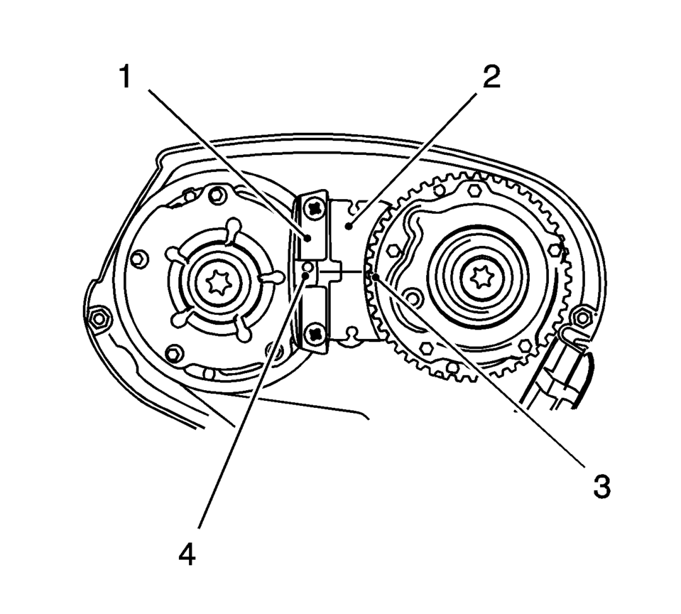
- Prepare the right half of the EN-6340 locking tool .
- Remove the 2 bolts (2).
- Remove the front panel (1) from the EN-6340 locking tool - right.
- The spot type marking (4) on the intake camshaft position actuator adjuster does not correspond to the groove of the EN-6340 locking tool - left (1) during this process, but must be somewhat above.
- The spot type marking (3) on the exhaust camshaft position actuator adjuster must correspond to the groove on EN-6340 locking tool - right (2).
- Insert the EN-6340 locking tool - left (1) and the EN-6340 locking tool - right (2) in the camshaft position actuator adjuster.
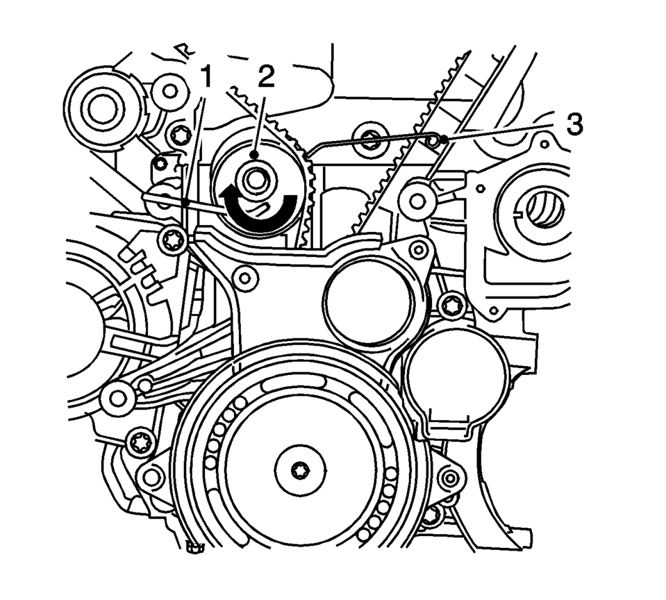
- Install the EN-6333 locking pin (1), apply tension to the timing belt tension roller (2) in the direction of the arrow. Install the EN-6333 locking pin (3).
- Mark timing belt in direction of rotation.
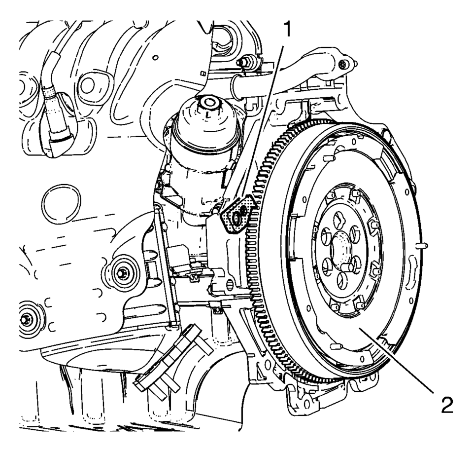
- Install the EN-652 flywheel holder (1), lock the flywheel (2) (or automatic transmission flex respectively) via the starter ring gear.
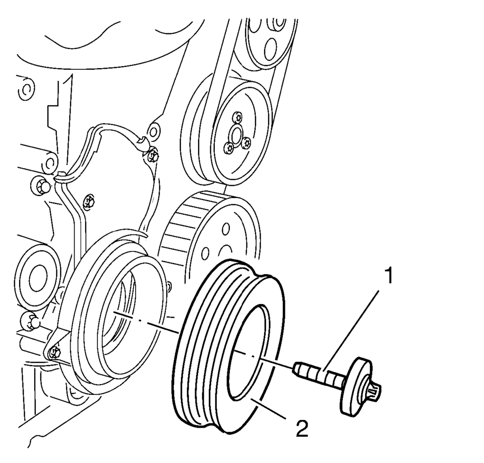
- Remove and DISCARD the crankshaft balancer bolt (1).
- Remove the crankshaft balancer (2).
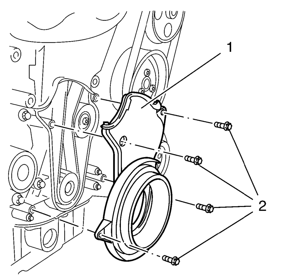
- Remove the 4 timing belt lower front cover bolts (2).
- Remove the timing belt lower front cover (1).
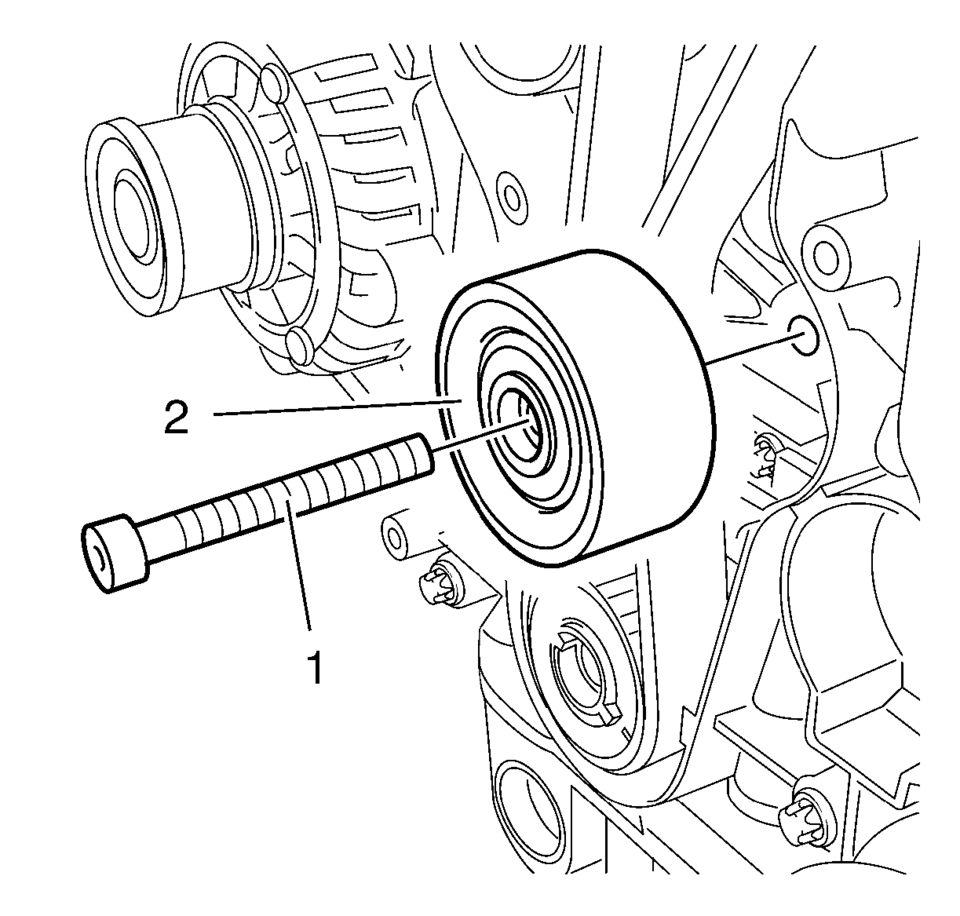
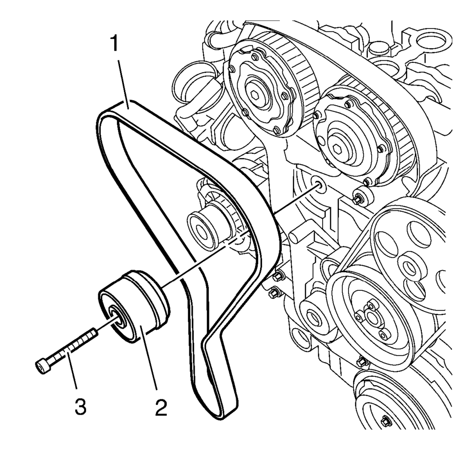
- Remove the timing belt idler pulley bolt (1).
- Remove the timing belt idler pulley (2).
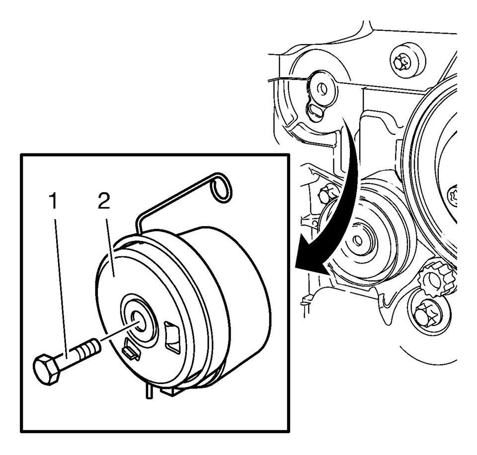
- Remove the tensioner bolt (1).
- Remove the timing belt tensioner (2).
- Remove the timing belt (1).
- Stop the timing belt tensioner (2).
- Remove the EN-652 flywheel holder to unlock the crankshaft.
- Turn the crankshaft 60° (A) against the direction of engine rotation.
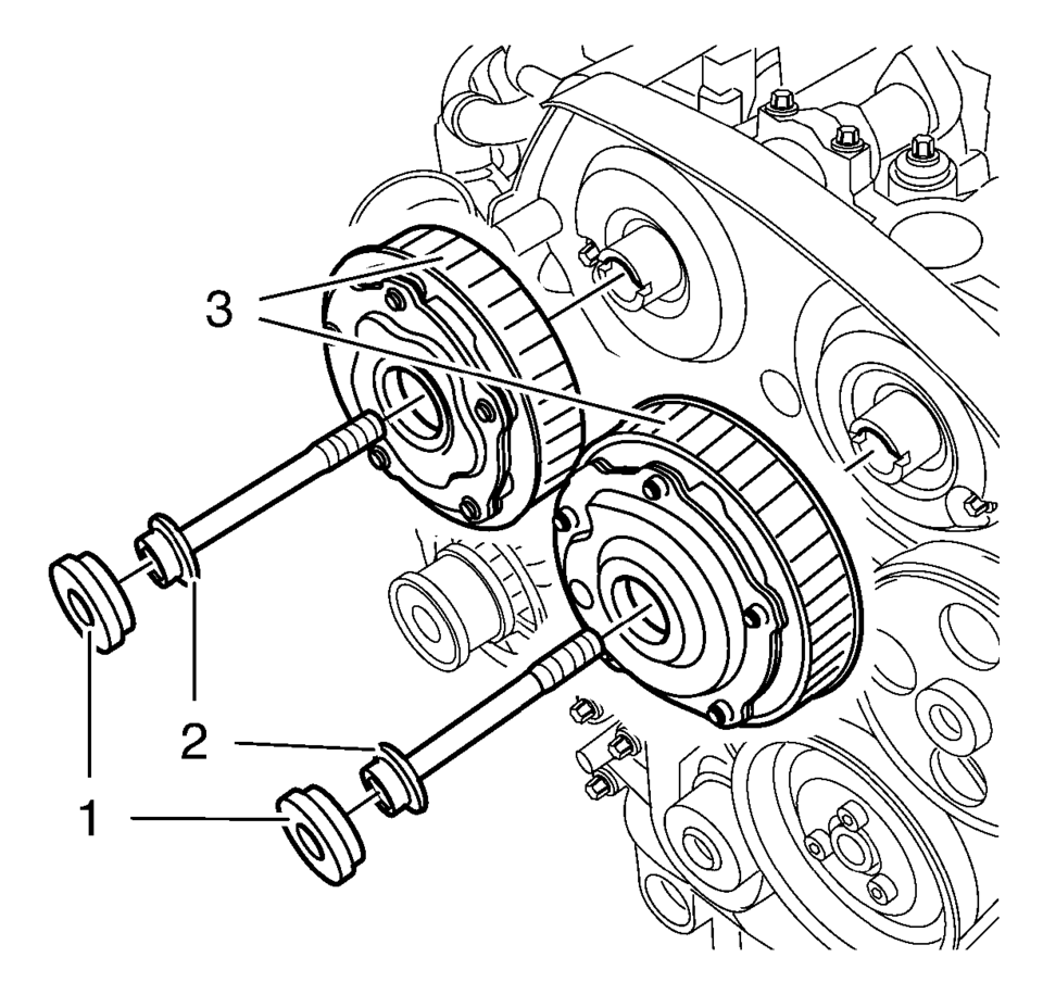
- Remove the 2 camshaft position actuator adjuster closure bolts (1).
- Loosen the camshaft position actuator adjuster bolts (2).
Hold at the appropriate camshaft hexagon.
- Remove and DISCARD the camshaft position actuator adjuster bolts (2) and the camshaft position actuator adjuster (3).
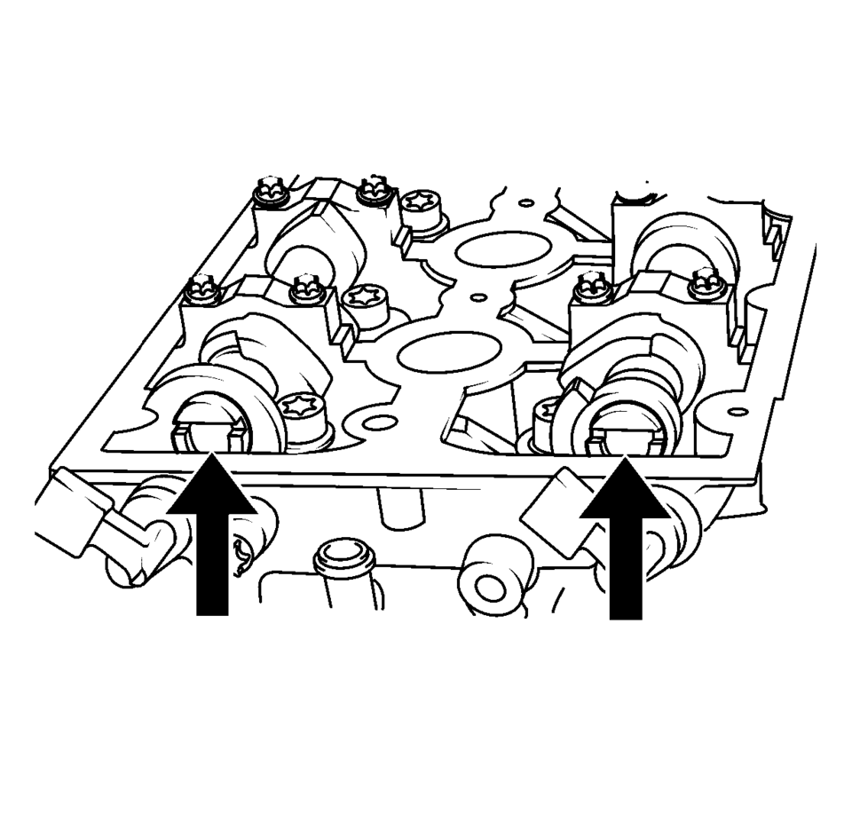
- Align the camshafts horizontally by the hexagon arrows, until the EN-6628-A locking tool can be inserted in both camshafts.
- Insert the EN-6628-A locking tool (1) into the camshafts.

Note:
The right half of the EN-6340 locking tool can be recognized by the lettering "right", arrow, on the tool.
Note:
Note:
A second technician is required.

- Installation Procedure
-
- Install the camshaft position actuator adjuster (3).
- Install NEW camshaft position actuator adjuster bolts (2).
- Tighten the camshaft position actuator adjuster bolts (2) in three passes:
Hold at the appropriate camshaft hexagon.
- First pass tighten to 65 Y (48 lb ft)
.
- Second pass to 120°
.
- Third pass to 15°
.
- Replace the camshaft position actuator adjuster seal rings.
- Install the 2 camshaft position actuator adjuster closure plugs (1)
and tighten to 30 Y (22 lb ft)
.
- Remove the EN-6628-A locking tool .
- Clean the timing belt tensioner thread.
- Install the timing belt tensioner (2) and tighten the NEW timing belt
tensioner bolt (1) to 20 Y (15 lb ft)
.
- Clean the timing belt idler pulley thread.
- Install the timing belt idler pulley (2) and tighten the NEW bolt (1)
to 25 Y (18 lb ft)
.
- Turn the crankshaft in the direction of engine rotation, by the crankshaft balancer bolt, to cylinder 1 TDC of combustion stroke.
- Install the EN-652 flywheel holder (1), lock the flywheel (2) (or automatic transmission flex respectively) via the starter ring gear.
- Insert the timing belt (1).
- Apply preliminary tension clockwise to the timing belt tension roller.
- Remove the EN-6333 locking pin .
- Release the tension on the timing belt tensioner.
- Install the lower front timing belt cover (1) and tighten the 4 bolts (2)
to 6 Y (53 lb in)
.
- Install the crankshaft balancer (2) and NEW bolt (1) and tighten in 3 passes using the EN-45059 sensor kit :
- First pass to 95 Y (70 lb ft)
.
- Second pass to 45°
.
- Third pass to 15°
.
- Remove the EN-652 flywheel holder to unlock the crankshaft.
- Remove the EN-6340 locking tool .
- Check position of the camshaft position actuator adjuster.
- Turn crankshaft 720°
in the direction of engine rotation by the crankshaft balancer bolt.
- Insert EN-6340 locking tool into camshaft timing gears.
- Insert the EN-6628-A locking tool (1) into the camshafts.
- Align camshafts by hexagon until EN-6628-A locking tool can be inserted in both camshafts.
- Check the crankshaft position.
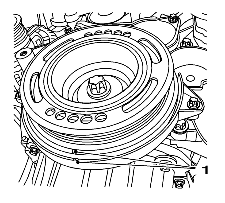
- Marking on crankshaft balancer must align with marking on timing belt lower cover, see mark (1).
- Remove the EN-6628-A locking tool .
- Install the camshaft cover. Refer to Camshaft Cover Installation.
- Install the timing belt upper front cover. Refer to Timing Belt Upper Front Cover Installation.
Note:
Do not tighten the camshaft adjuster bolts.
Caution:
Refer to Fastener Caution.
Caution:
Refer to Torque-to-Yield Fastener Caution.
Note:
A second technician is required.

Note:
The timing belt drive gear and oil pump housing must align.
Note:
Observe direction of rotation.
Note:
Note marking, camshaft position actuator adjuster.
 Camshaft Timing Chain Replacement
Special Tools
EN-955 Locking Pin
For equivalent regional tools. Refer to Special Tools.
Removal Procedure
Remove the engine front cover. Refer to Engine Front Cover with Oil
Pum ...
 Timing Belt Center Front Cover Installation
Install the timing belt center front cover (1) to the timing belt rear cover
at 2 locations. ...
Other materials:
SIR Seatbelt Pretensioner Handling Warning
Warning: When carrying an undeployed inflatable restraint seat belt
retractor pretensioner:
Do not carry the seat belt pretensioner by the seat belt webbing or
pigtail connector, if equipped.
Carry the seat belt pretensioner by the housing, keeping hands and fingers
away fro ...
Brake Warning System Description and Operation
Brake Warning Indicator
Brake Warning Block Diagram
B80Park
Brake
SwitchB20Brake
Fluid Level
SwitchK9Body
Control
ModuleP16Instrument
Cluster
Hard-Wired
Serial D ...
Heater and Air Conditioning Evaporator Case Replacement
Air Conditioning (A/C) Evaporator Case Assembly Replacement
Callout
Component Name
Preliminary Procedure
Remove the instrument panel tie bar. Refer to Instrument Panel Tie
Bar Replacement.
Remove HVAC module. Refer to Hea ...

0.0067