Chevrolet Sonic Repair Manual: Tire and Wheel Assembly Runout Measurement - On-Vehicle
- Raise and support the vehicle.
- Closely inspect each tire for proper and even bead seating.
- If any of the tire beads were not properly or evenly seated, reseat the tire bead, then proceed to step 4. Refer to Tire and Wheel Removal and Installation.
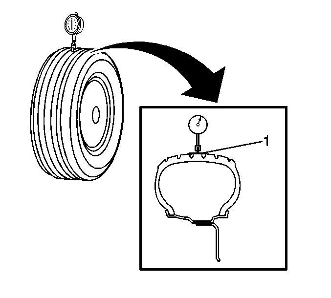
- Wrap the circumference of each tire with tape (1) in the center tread area.
Wrapping the tread with tape allows for a smooth and accurate reading of radial runout to be obtained.
- Position the dial indicator on the taped portion of the tire tread such that the dial indicator is perpendicular to the tire tread surface.
- Slowly rotate the tire and wheel assembly one complete revolution in order to find the low spot.
- Set the dial indicator to zero at the low spot.
- Slowly rotate the tire and wheel assembly one more complete revolution and
measure the total amount of radial runout.
Specification
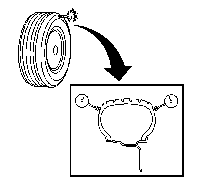
Maximum tire and wheel assembly radial runout – measured on-vehicle: 1.52 mm (0.060 in) - Position the dial indicator on a smooth portion of the tire sidewall, as close to the tread as possible, such that the dial indicator is perpendicular to the tire sidewall surface.
- Slowly rotate the tire and wheel assembly one complete revolution in order to find the low spot. Ignore any jumps or dips due to sidewall splices.
- Set the dial indicator to zero at the low spot.
- Slowly rotate the tire and wheel assembly one more complete revolution and
measure the total amount of lateral runout. Ignore any jumps or dips due to
sidewall splices and attain an average runout measurement.
Specification
Maximum tire and wheel assembly lateral runout – measured on-vehicle: 1.52 mm (0.060 in) - Repeat steps 4 through 12 until all of the tire and wheel assembly radial and lateral runout measurements have been taken.
- Lower the vehicle.
 Tire and Wheel Assembly Runout Measurement - Off Vehicle
Raise and support the vehicle.
Mark the location of the wheels to the wheel studs and mark the specific
vehicle position on each tire and wheel – LF, LR, RF, RR.
Remove the tire and wheel ...
 Tire and Wheel Assembly-to-Hub/Axle Flange Match-Mounting
Note: After remounting a tire and wheel assembly to a hub/axle flange,
remeasure the tire and wheel assembly on-vehicle runout in order to verify that
the amount of runout has been reduced an ...
Other materials:
If the Off Indicator Is Lit for an Adult-Size Occupant
If a person of adult size is sitting in the front outboard passenger seat, but
the off indicator is lit, it could be because that person is not sitting properly
in the seat. Use the following steps to allow the system to detect that person and
enable the front outboard passenger frontal airb ...
Replacing Brake System Parts
The braking system on a vehicle is complex. Its many parts have to be of top
quality and work well together if the vehicle is to have really good braking. The
vehicle was designed and tested with top-quality brake parts. When parts of the
braking system are replaced, be sure to get new, approv ...
Air Conditioning Clutch Assembly Replacement (LDE/LUW/LWE)
Air Conditioning Clutch Assembly Replacement
Callout
Component Name
Preliminary Procedure
Remove the air conditioning compressor. Refer to
Air Conditioning Compressor Replacement.
1
Air Condit ...

0.0054