Chevrolet Sonic Repair Manual: Transmission Mount Replacement - Left Side
- Removal Procedure
-
- Remove the battery tray. Refer to Battery Tray Replacement.
- Install the engine support fixture. Refer to Engine Support Fixture.
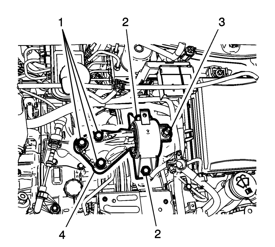
- Remove and DISCARD the left transmission mount to bracket bolts (1).
- Remove the left transmission mount to body bolts (2).
- Remove the left transmission mount to body nut (3).
- Remove the transmission mount (4) from the vehicle.
- Installation Procedure
-
- Install the left transmission mount (4) to the vehicle.
- Install the transmission mount to body bolts (2) and
tighten to 58 Y (43 lb ft)
.
- Install the transmission mount to body nut (3) and
tighten to 58 Y (43 lb ft)
.
- Install the NEW left transmission mount to transmission
bolts (1) and tighten to 50 Y (37 lb ft)
plus 60?5 degrees
.
- Remove the engine support fixture. Refer to Engine Support Fixture.
- Install the battery tray. Refer to Battery Tray Replacement.
Caution:
Refer to Fastener Caution.
 Transmission Mount Bracket Replacement - Rear
Removal Procedure
Raise and support the vehicle. Refer to
Lifting and Jacking the Vehicle.
Using a suitable jack stand, support the rear of the
transmission.
Remove ...
 Front Wheel Drive Shaft Seal Replacement - Right Side
Front Wheel Drive Shaft Seal Replacement - Right Side
Callout
Component Name
Preliminary Procedures
Raise and support the vehicle. ...
Other materials:
Tire Pressure Monitor System
The Tire Pressure Monitor System (TPMS) uses radio and sensor technology to check
tire pressure levels. The TPMS sensors monitor the air pressure in your tires and
transmit tire pressure readings to a receiver located in the vehicle.
Each tire, including the spare (if provided), should be check ...
Operation
Radio Controls without Touchscreen
The infotainment system is operated by using the pushbuttons, multifunction
knobs, menus shown on the display, and steering wheel controls, if equipped.
Turning the System On or Off
O /VOL (Power/Volume)
Press to turn t ...
Low and Reverse and 1-2-3-4 Clutch Housing, and 1-2-3-4 Clutch Plate Installation
(6T40/45/50)
Low and Reverse and 1-2-3-4 Clutch Housing, and 1-2-3-4 Clutch Plate
Installation
Callout
Component Name
1
Low and Reverse and 1??? Clutch Housing
Note: The longer legs face the bottom of the case and the
...

0.0064