Chevrolet Sonic Repair Manual: Center Pillar Reinforcement Replacement
- Removal Procedure
-
- Disable the SIR system. Refer to SIR Disabling and Enabling.
- Disconnect the negative battery cable. Refer to Battery Negative Cable Disconnection and Connection.
- Remove all related panels and components.
- Visually inspect the damage. Repair as much of the damage as possible.
- Remove the sealers and anti-corrosion materials from the repair area, as necessary. Refer to Anti-Corrosion Treatment and Repair.
- Locate and mark all the necessary factory welds of the center pillar reinforcement.
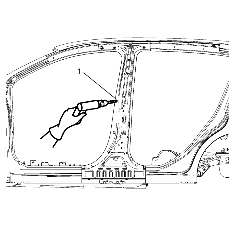
- Drill all factory welds (1). Note the number and location of welds for installation of the service assembly.
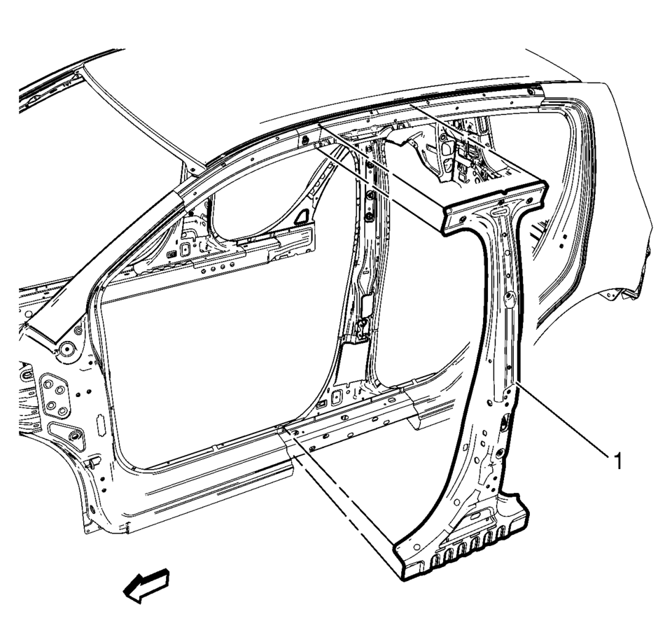
- Remove the damaged center pillar reinforcement (1).
Warning:
Refer to Approved Equipment for Collision Repair Warning.
Warning:
Refer to Glass and Sheet Metal Handling Warning.
Note:
The center pillar upper stiffener is made of Dual Phase Steel and should be replaced only at factory joints. Repairing or sectioning of this part is not recommended. Refer to Dual Phase Steel.
- Installation Procedure
-
- Prepare all mating surfaces as necessary.
- Align the center pillar reinforcement.
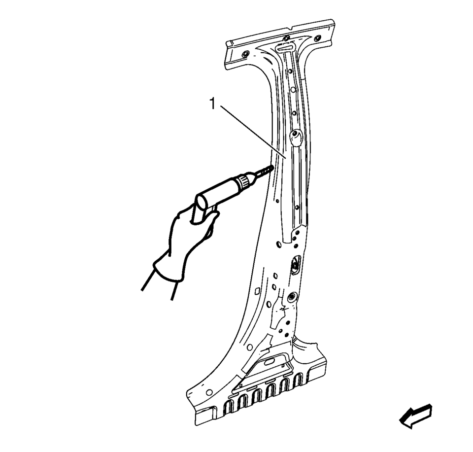
- Drill a 8?€‰mm (5/16?€‰in)
holes for plug welding along the edges of the center pillar reinforcement as noted from the original panel (1).
- Clean and prepare the attaching surfaces for welding.
- Position the center pillar reinforcement on the vehicle (1).
- Verify the fit of the center pillar reinforcement.
- Clamp the center pillar reinforcement into position.
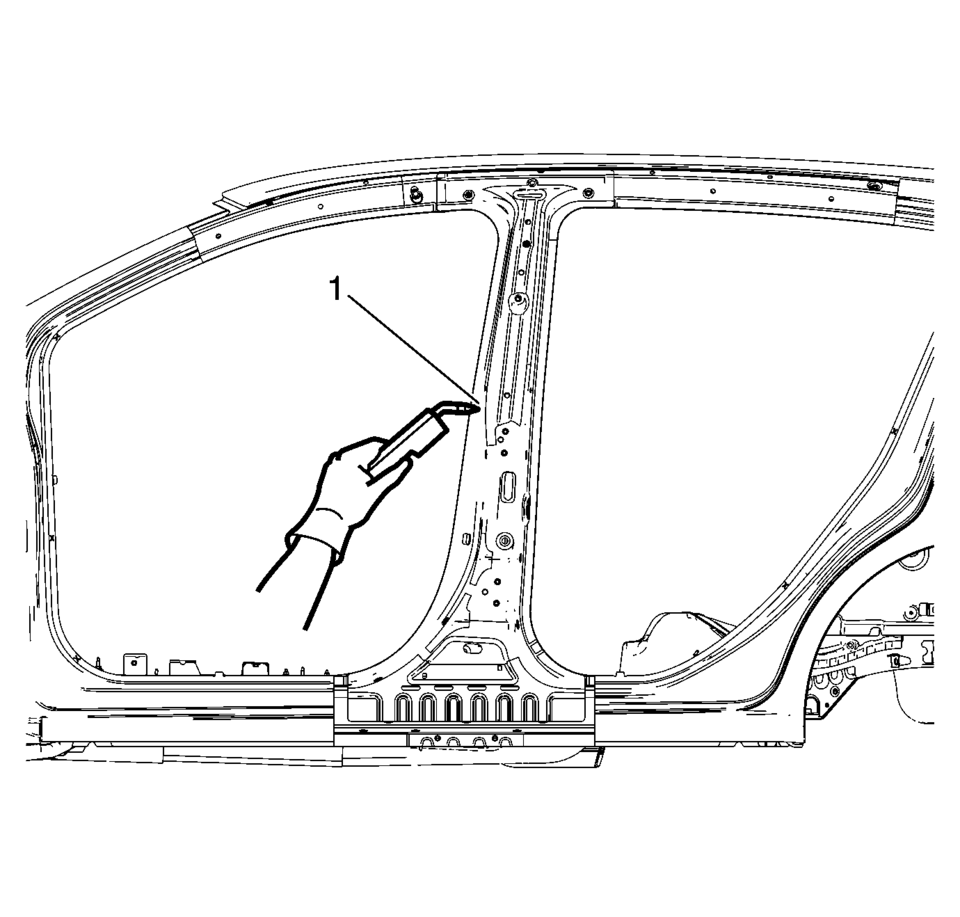
- Plug weld accordingly (1).
- Apply the sealers and anti-corrosion materials to the repair area, as necessary. Refer to Anti-Corrosion Treatment and Repair.
- Paint the repaired area. Refer to Basecoat/Clearcoat Paint Systems.
- Install all related panels and components.
- Connect the negative battery cable. Refer to Battery Negative Cable Disconnection and Connection.
- Enable the SIR system. Refer to SIR Disabling and Enabling.
 Special Tools
Illustration
Tool Number/ Description
EN-45059
J-45059
Angle Meter
...
 Drivetrain and Front Suspension Frame Skid Plate Replacement
Removal Procedure
Raise and support the vehicle. Refer to Lifting and Jacking the Vehicle.
Remove the mounting bolts?€‰(1) for the front suspension frame skid
p ...
Other materials:
Trip Odometer
The trip odometer measures the distance the vehicle has been driven since the
function was last reset.
Press the reset stem in the lower right of the tachometer to toggle between the
odometer and the trip odometer. To reset the trip odometer to zero, press and hold
the reset stem while the ...
Exhaust Front Pipe Replacement (LUV,LUW)
Removal Procedure
Warning: Refer to Exhaust Service Warning.
Remove the drivetrain and front suspension frame skid plate. Refer to
Drivetrain and Front Suspension Frame Skid Plate Replacement.
Disconnect the heated oxygen sensor-2. Refer to Heated Oxygen Sensor
Rep ...
Engine Replacement (Manual Transmission)
Special Tools
J-45859 Wheel Drive Shaft Remover .
CH-807 Closure Plugs .
For equivalent regional tools, refer to Special Tools.
Removal Procedure
Remove the battery and battery tray. Refer to
Battery Tray Replacement.
Relieve the fuel system pressure. Refer to
...

0.0081