Chevrolet Sonic Repair Manual: Differential Case Assemble
Special Tools
- J-810721 Axle Shaft Seal Remover Support Base
- R-0407011 Bearing Race Remover
- R-0407012 Differential Carrier Cone Bearing Cap Driver
- R-0007761 Universal Handle for Pullers and Installers
- S-9407194 Speed Sensor Impeller Ring Installer
- S-9407195 Pinion Gear Case Bearing Installer
- S-9707500 Seal Installer
For equivalent regional tools, refer to Special Tools.
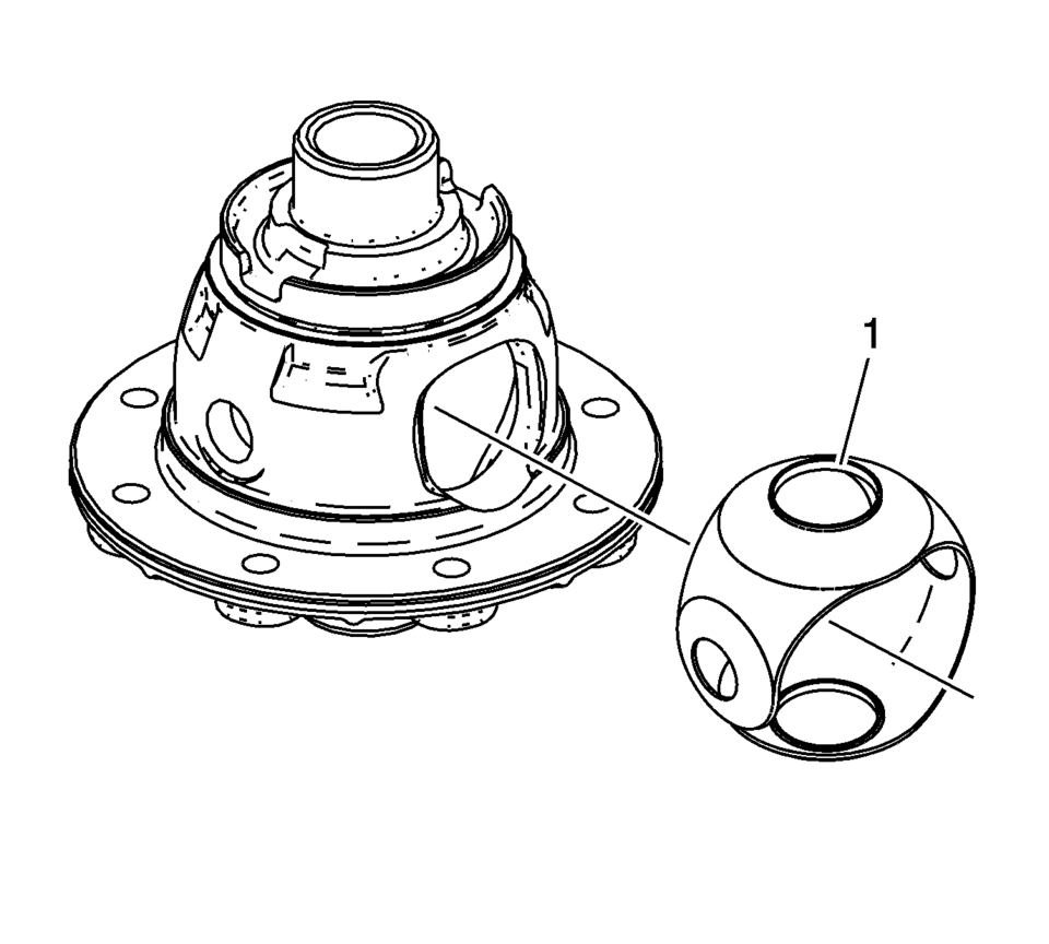
- Install the front differential pinion and side gear thrust washer. It must be possible to insert the collar (1) of the thrust washer into the guide for the pinion gears in the housing.
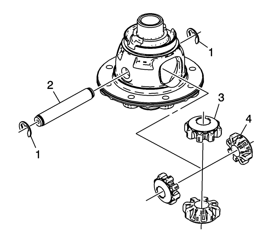
- Install the front differential pinion gears (3) and side gears (4).
- Install the front differential pinion gear shaft (2) and the pinion gear shaft retaining washers (1).
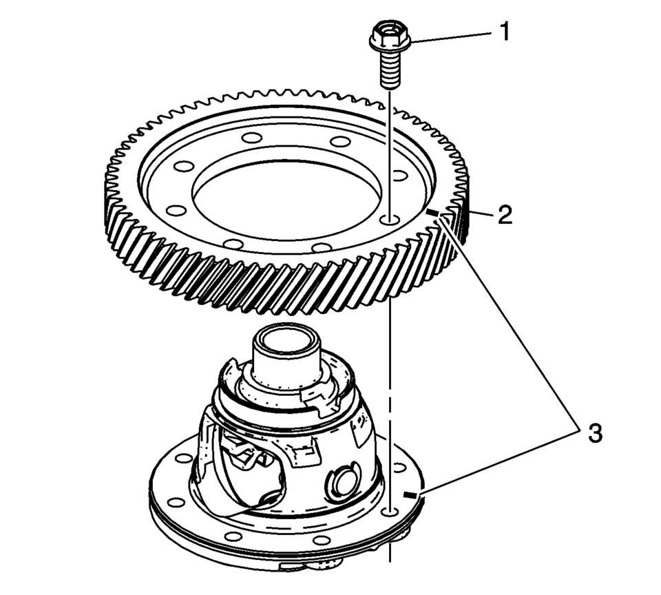
- If both components are reused align the assembly marks (3).
- Install the front differential ring gear (2).
- Install the front differential ring gear bolts (1). Tighten to 90 N•m
(66.4 lb ft)
.
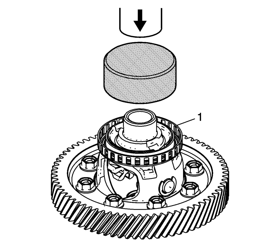
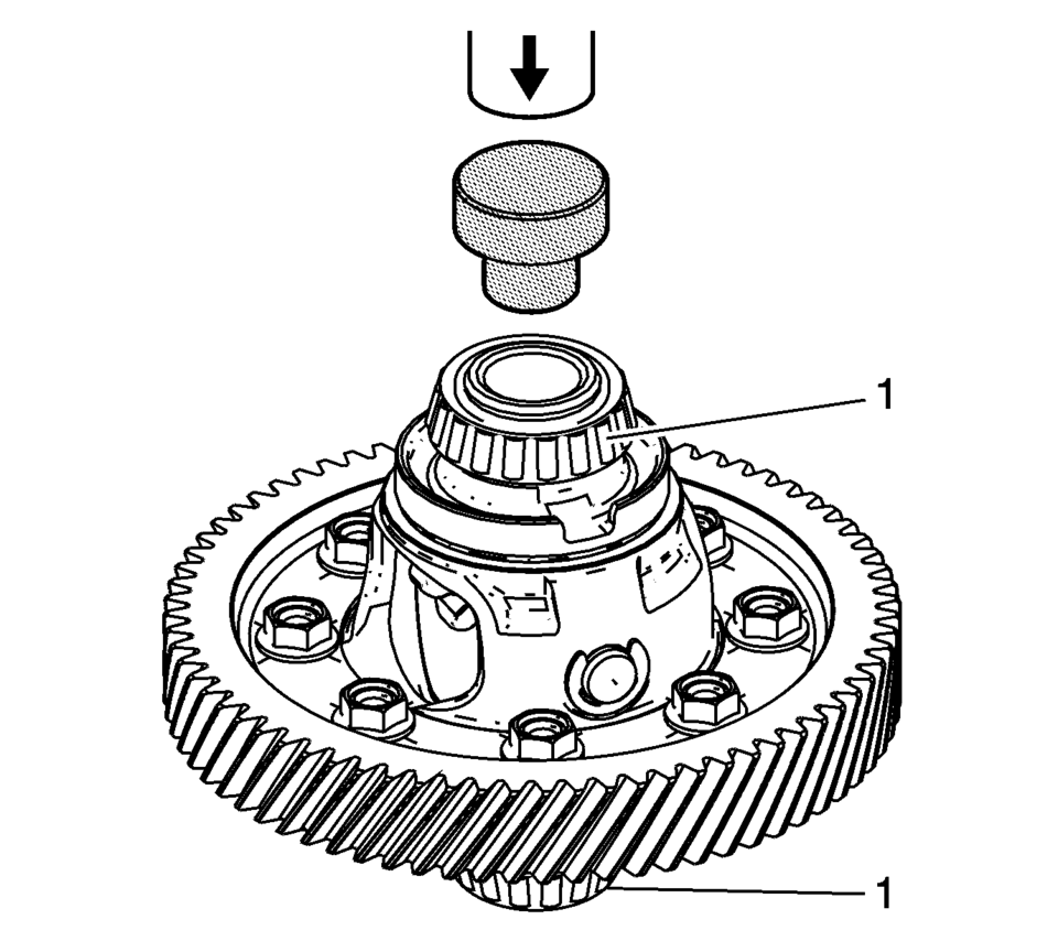
- Install the ring front wheel speed sensor reluctor wheel (1) using the S-9407194 installer and a hydraulic press.
- Install the front differential bearing assemblies (1) using the S-9407195 installer and a hydraulic press.
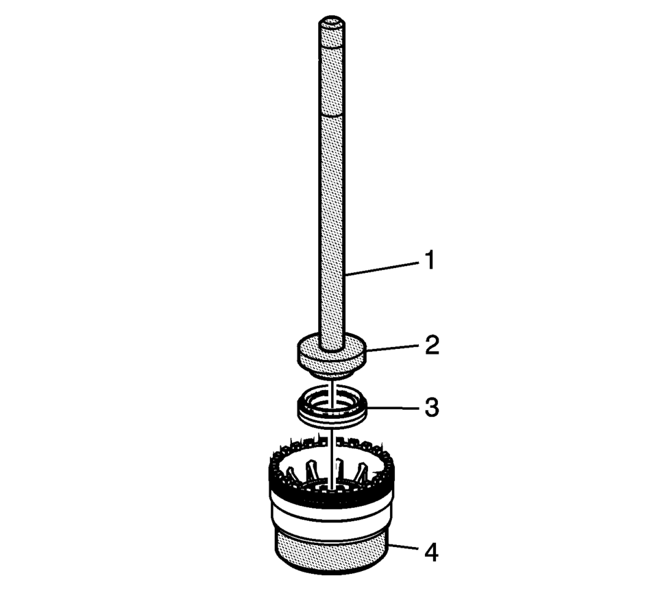
- Install the front wheel drive shaft oil seal (3) using the R-0007761 handle (1), S-9707500 seal installer (2), and the J-810721 support base (4).
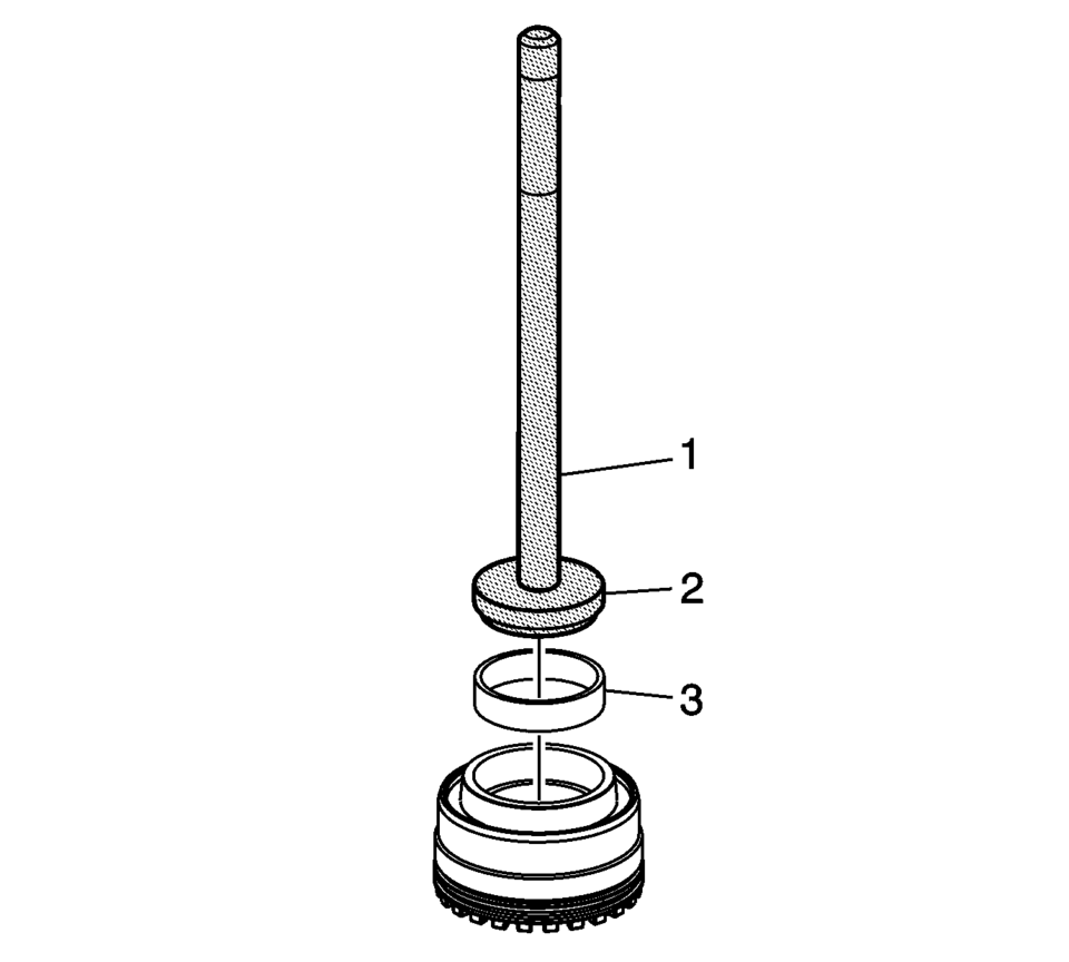
- Install the front differential bearing race (3) using the R-0007761 handle (1) and the R-0407012 driver (2).
Note:
Lubricate rotating parts on their bearing, running, seating, and pressure surfaces using transmission fluid.
Warning:
Refer to Safety Glasses Warning.
 Differentials
...
 Differential Case Disassemble
Special Tools
6-9607346 Sensor Ring Gear Puller
J-810704 Steering Column Center Bar Puller
J-810721 Axle Shaft Seal Remover Support Base
R-0006749 Support Base
R-0407011 Bearing Race Rem ...
Other materials:
Rear Window Replacement
Special Tools
BO-24402-A Glass Sealant Remover (Cold Knife)
BO-39032 Stationary Glass Removal Tool
Use an adhesive that is approved by GM
For equivalent regional tools, refer to Special Tools
Removal Procedure
Warning: If a window is cracked but still intact, crisscros ...
Front Seat Outboard Seat Back Airbag Replacement
Front Seat Outboard Seat Back Airbag Replacement
Callout
Component Name
Warning: Following the deployment of a side impact air bag,
inspect the following parts for damage. Replace these parts if necessary:
...
Warm Up Three-Way Catalytic Converter Removal
Disconnect the heated oxygen sensor wiring harness (3) from retainer clip.
Remove the 2 catalytic converter to catalytic converter bracket nuts (4)
and (6).
Loosen the three way warm up catalytic converter V-clamp (1).
Remove the three way warm up ...

0.0052