Chevrolet Sonic Repair Manual: Dimensions - Body (4NB)
Point-to-point measurements are for reference only. All measurements are given in millimeters. Use these measurements for diagnosing and estimating. Point-to-point measurements are duplicated with tram bar pointers set at equal lengths. All die marks, holes, slots, and fasteners are measured to the center. All dimensions are symmetrical unless otherwise specified.
- Point-to-Point Measurements
-
- Front End
__ ez \c_ _l -- .: _. .:
(1) 926?‚ā¨‚Äįmm (2) 926?‚ā¨‚Äįmm
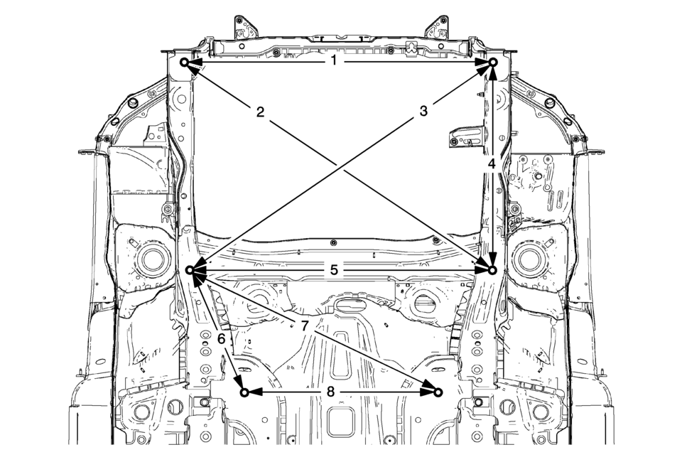
- Engine Compartment

(1) 1201?‚ā¨‚Äįmm (2) 944?‚ā¨‚Äįmm (3) 599?‚ā¨‚Äįmm (4) 1300?‚ā¨‚Äįmm (5) 1409?‚ā¨‚Äįmm
- Front End Lower
(1) 928?‚ā¨‚Äįmm (2) 1122?‚ā¨‚Äįmm (3) 1110?‚ā¨‚Äįmm (4) 633?‚ā¨‚Äįmm (5) 910?‚ā¨‚Äįmm (6) 440?‚ā¨‚Äįmm (7) 852?‚ā¨‚Äįmm (8) 584?‚ā¨‚Äįmm
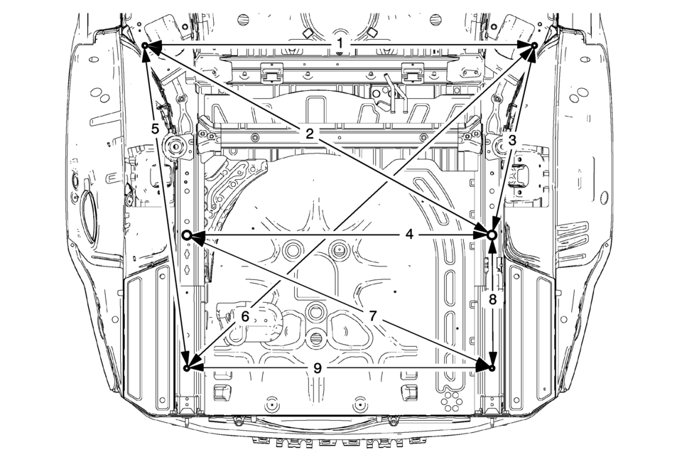
- Rear End Lower
ii
(1) 1233?‚ā¨‚Äįmm (2) 1259?‚ā¨‚Äįmm (3) 627?‚ā¨‚Äįmm (4) 966?‚ā¨‚Äįmm (5) 1035?‚ā¨‚Äįmm (6) 1504?‚ā¨‚Äįmm (7) 1052?‚ā¨‚Äįmm (8) 417?‚ā¨‚Äįmm (9) 965?‚ā¨‚Äįmm
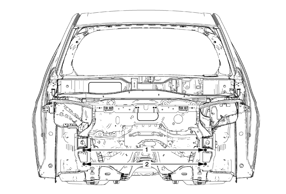
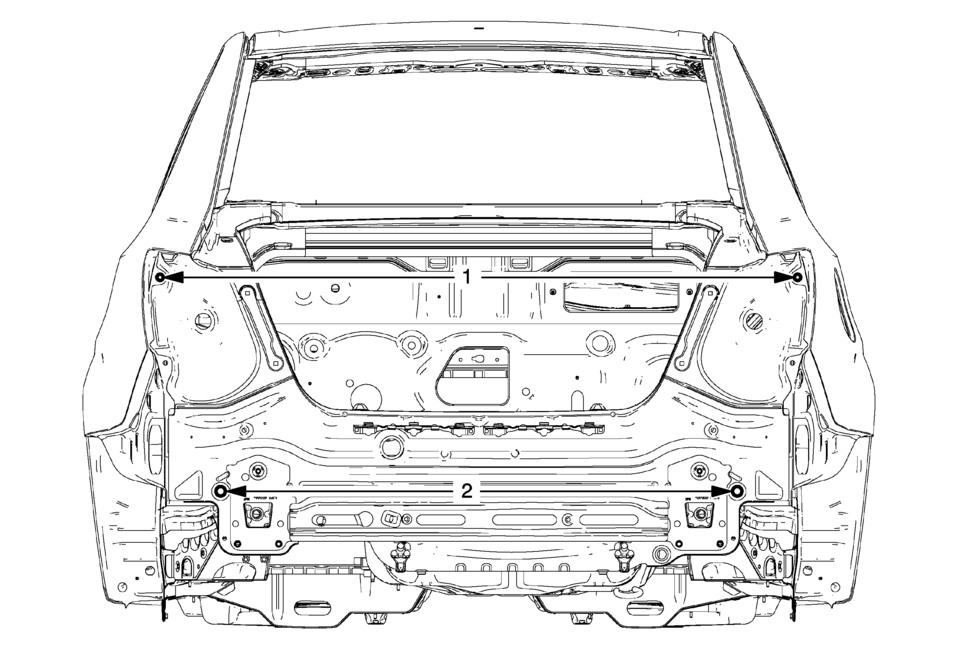
- Rear End
.. \.. 1/
(1) 1396?‚ā¨‚Äįmm (2) 1130?‚ā¨‚Äįmm
- Side
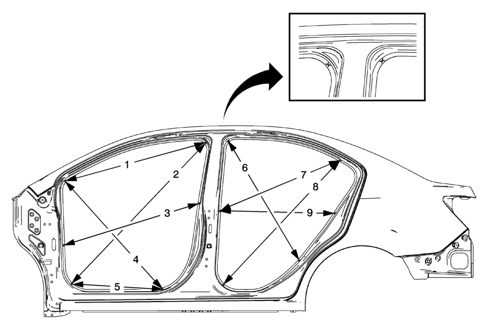
(1) 985?‚ā¨‚Äįmm (2) 1319?‚ā¨‚Äįmm (3) 955?‚ā¨‚Äįmm (4) 981?‚ā¨‚Äįmm (5) 611?‚ā¨‚Äįmm (6) 946?‚ā¨‚Äįmm (7) 886?‚ā¨‚Äįmm (8) 1155?‚ā¨‚Äįmm (9) 776?‚ā¨‚Äįmm
 Body Waterleak Repair
Warning: If the vehicle interior is exposed to moisture and becomes
soaked up to the level of the sensing and diagnostic module (SDM), the SDM and
SDM harness connector must be replaced. ...
 Dimensions - Body (5HB)
Point-to-point measurements are for reference only. All measurements are given
in millimeters. Use these measurements for diagnosing and estimating. Point-to-point
measurements are duplicated with ...
Other materials:
Rear Brake Hose Replacement (Body to Axle - Disc Brake)
Removal Procedure
Warning: Refer to Brake Dust Warning.
Warning: Refer to Brake Fluid Irritant Warning.
Raise and support the vehicle. Refer to Lifting and Jacking the Vehicle.
Remove the tire and wheel assembly. Refer to Tire and Wheel Removal
and Install ...
Tire and Wheel Assembly Runout Measurement - Off Vehicle
Raise and support the vehicle.
Mark the location of the wheels to the wheel studs and mark the specific
vehicle position on each tire and wheel ‚Äď LF, LR, RF, RR.
Remove the tire and wheel assemblies from the vehicle.
Closely inspect each tire for proper and even bead seating.
If an ...
Front Wheel Drive Shaft Seal Replacement - Left Side
Front Wheel Drive Shaft Seal Replacement - Left Side
Callout
Component Name
Preliminary Procedures
Raise and support the vehicle. Refer to Lifting and Jacking the
Vehicle.
Remove the left wheel drive shaft. Refer to Front ...

0.0048