Chevrolet Sonic Repair Manual: Drum Brake Adjusting Hardware Inspection
- Visually inspect the adjuster actuator spring (1) for the following conditions:
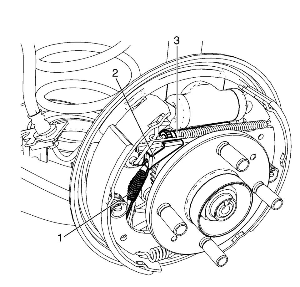
Warning:
Refer to Brake Dust Warning.
- Excessive stretching
- Excessive bending
- Excessive corrosion
- Broken
- Missing
- Bent
- Broken
- The lever engagement surface excessively worn
- Excessively bent or broken spring attachment tab
- Missing
- Bent
- Broken
- Seized adjuster wheel threads
- Excessively worn, damaged, or missing teeth
 Brake Drum Surface and Wear Inspection
Special Tools
CH-8001 Dial Indicator Set
For equivalent regional tools, refer to Special Tools.
Warning: Refer to Brake Dust Warning.
With the brake drum removed, clean the brake sh ...
 Drum Brake Adjusting Hardware Replacement (J93, J94)
Removal Procedure
Warning: Refer to Brake Dust Warning.
Raise and support the vehicle. Refer to Lifting and Jacking the Vehicle.
Remove the tire and wheel assembly. Re ...
Other materials:
Driver or Passenger Seat Back Cover and Pad Replacement
Driver or Passenger Seat Back Cover and Pad Replacement
Callout
Component Name
Warning: Refer to SIR Warning.
Warning: Do not repair or replace the seat stitching or seams
in the seat back trim cover with an ...
Front Differential Carrier Cleaning and Inspection
Front Differential Carrier Cleaning and Inspection
Callout
Component Name
Caution: After cleaning the transmission components, allow
to air dry. Do not use cloth or paper towels in order to dry any transmission
compo ...
NISSAN All-Mode 4WD system
The NISSAN All-Mode 4WD system in the Nissan Armada is engineered to deliver
maximum versatility and control by offering multiple selectable drive modes, including
AUTO, 4H, and 4L (if equipped). This intelligent system allows the driver to adapt
the Nissan Armada to a wide range of road and o ...

0.0097