Chevrolet Sonic Repair Manual: Engine Oil Cooler Replacement
- Removal Procedure
-
- Disconnect battery negative cable. Refer to Battery Negative Cable Disconnection and Connection.
- Drain engine coolant. Refer to Cooling System Draining and Filling
- Remove the turbocharger oil feed pipe. Refer to Turbocharger Oil Feed Pipe Replacement.
- Remove the catalytic converter. Refer to Catalytic Converter Replacement.
- Lower vehicle.
- Remove the air cleaner outlet duct. Refer to Air Cleaner Outlet Duct Replacement.
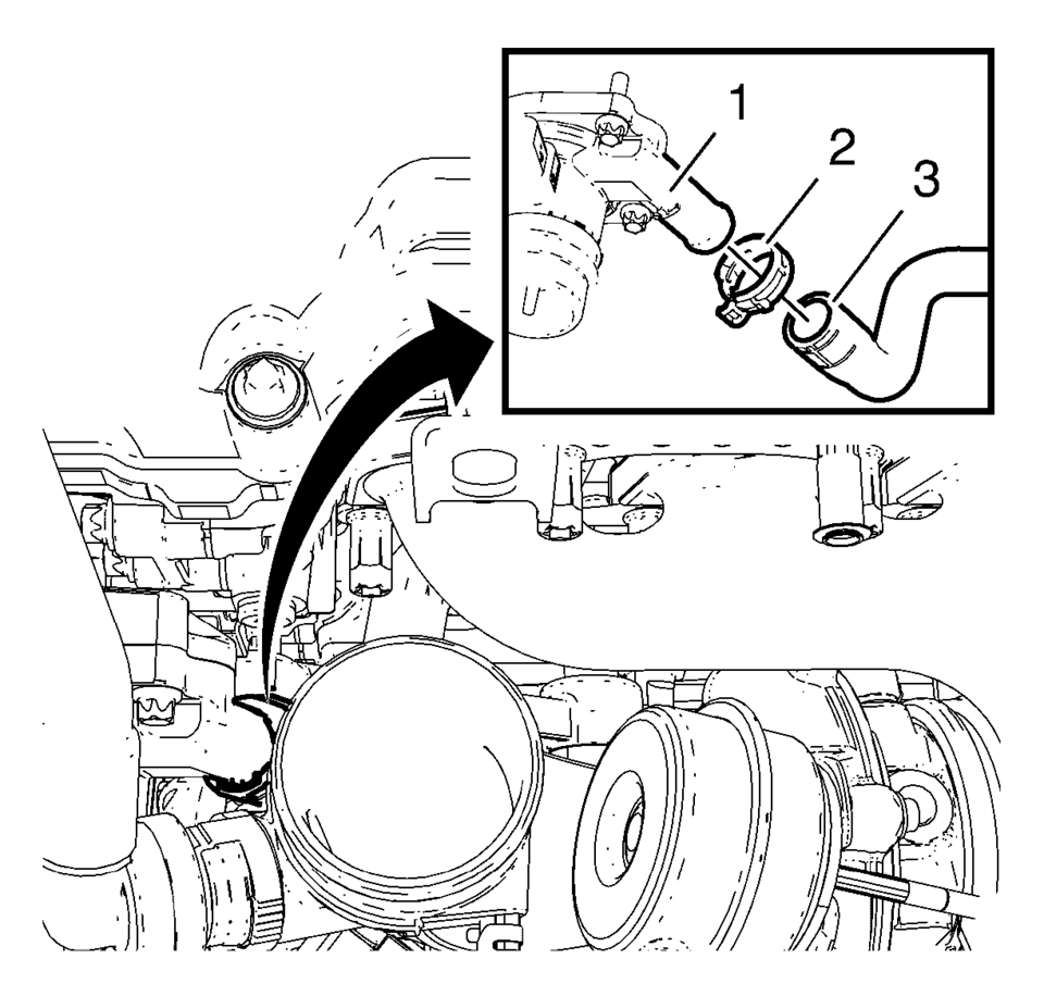
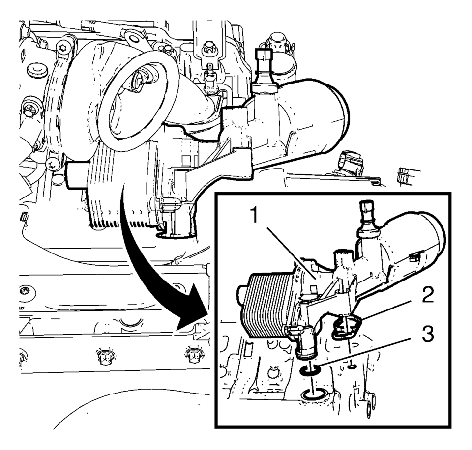
- Remove the oil cooler outlet hose clamp (2).
- Remove the oil cooler outlet hose (3) from the thermostat housing (1).
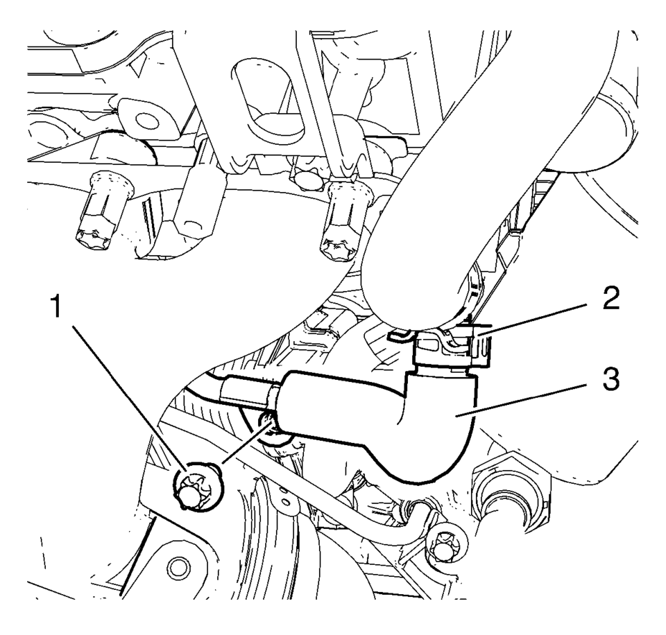
- Remove the turbocharger coolant return pipe bolt (1) from the oil cooler housing.
- Remove the turbocharger coolant return pipe clamp (2).
- Remove the turbocharger coolant return pipe (3) from the oil cooler inlet pipe.
- Disconnect the oil pressure indicator switch wiring harness plug.
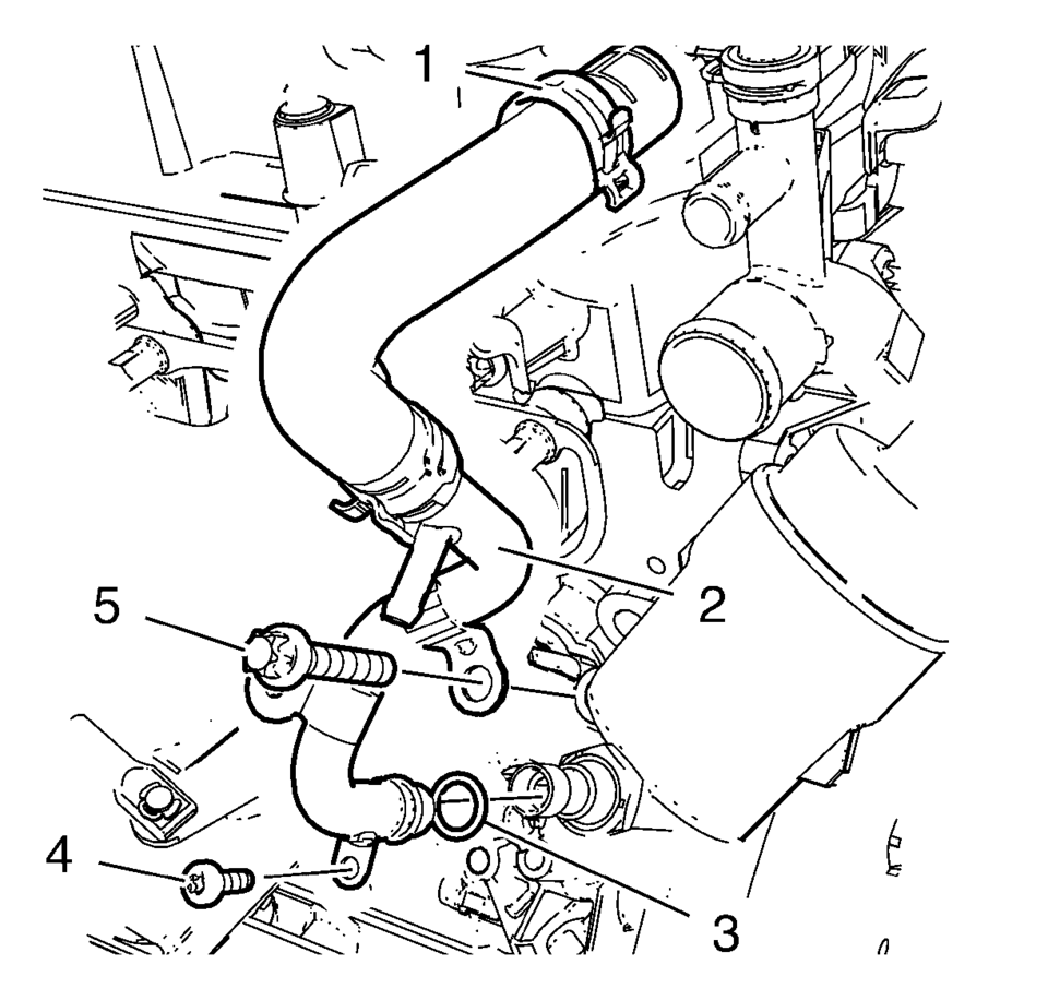
- Remove the oil cooler inlet hose clamp (1) and remove the oil cooler inlet hose from the water outlet.
- Remove the engine oil cooler bolt (5).
- Remove the engine oil cooler inlet pipe bolt (4).
- Remove the engine oil cooler inlet pipe (2) and the seal ring (3).
- Raise vehicle.
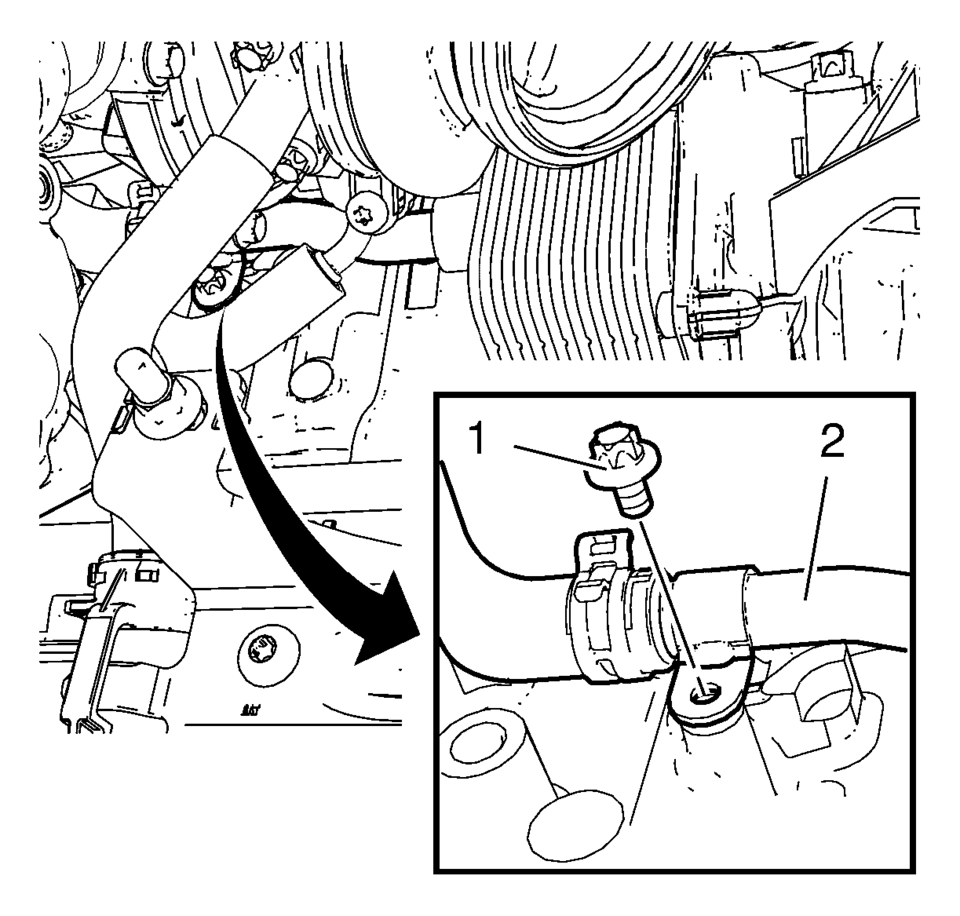
- Remove the oil cooler outlet pipe bolt (1) from the engine block.
- Remove the oil cooler outlet pipe (2) in compound with the oil cooler outlet hose.
- Lower vehicle.
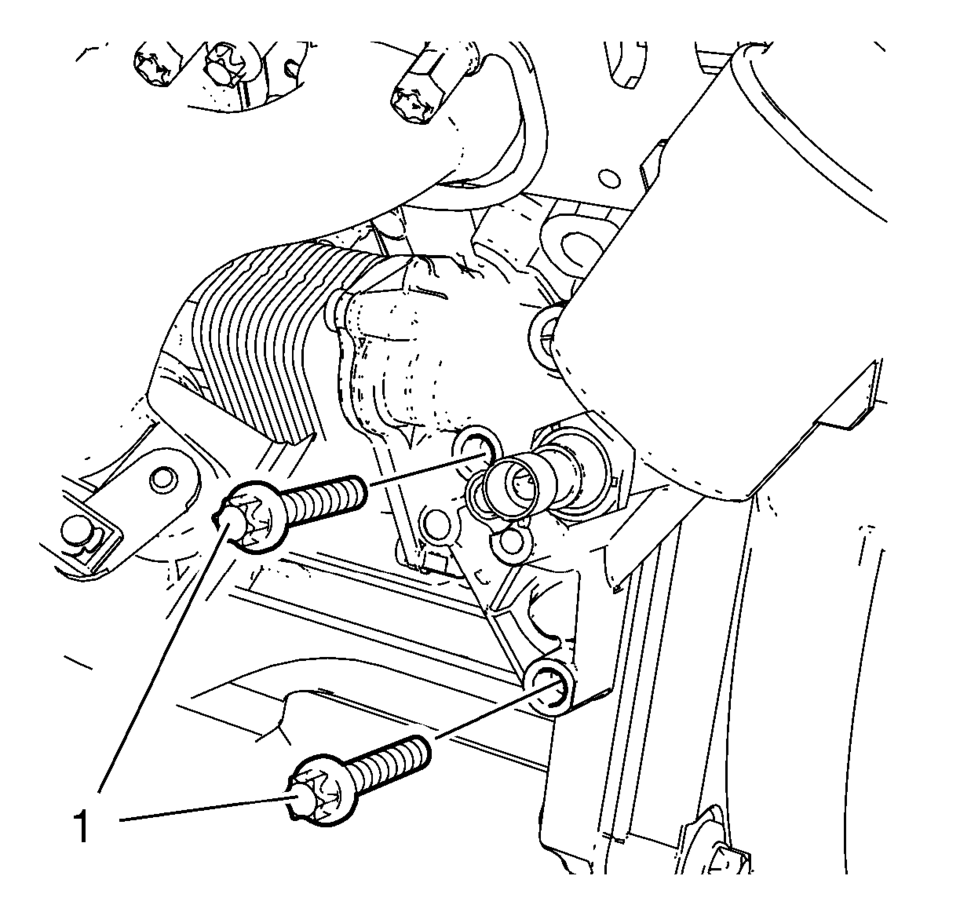
- Remove the 2 oil cooler bolts (1).
- Raise vehicle.
- Remove the oil cooler (1) in compound with the oil cooler gasket (2) and the seal ring (3).
- Remove the oil pressure indicator switch from the oil cooler.
Note:
Do not move the turbocharger coolant return pipe too much. An excessive moving of the turbocharger coolant return pipe could cause leakage.
rh\;,/
- Installation Procedure
-
- Install the oil pressure indicator switch to the oil cooler. Use a NEW seal ring.
- Tighten the oil pressure indicator switch to 20 Y (15 lb ft)
.
- Clean the sealing surfaces.
- Install the oil cooler (1) in compound with a NEW oil cooler gasket (2) and a NEW seal ring (3).
- Lower vehicle.
- Install the 2 oil cooler bolts (1) and hand tighten.
- Install the engine oil cooler inlet pipe (2) in compound with a NEW seal ring (3).
- Install the oil cooler inlet hose to the water outlet and install the oil cooler inlet hose clamp (1).
- Install the engine oil cooler bolt (5).
- Install the engine oil cooler inlet pipe bolt (4) and tighten to
10 Y (89 lb in)
.
- Tighten the 3 engine oil cooler bolts to 20 Y (15 lb ft)
.
- Install the turbocharger coolant return pipe (3) to the oil cooler inlet pipe.
- Install the turbocharger coolant return pipe clamp (2).
- Install turbocharger coolant return pipe bolt (1) and tighten to
10 Y (89 lb in)
.
- Connect the oil pressure indicator switch wiring harness plug.
- Raise vehicle.
- Install the oil cooler outlet pipe (2) in compound with the oil cooler outlet hose to the oil cooler.
- Install the oil cooler outlet pipe bolt (1) to the engine block and
tighten to 10 Y (89 lb in)
.
- Install the catalytic converter. Refer to Catalytic Converter Replacement.
- Install the oil cooler outlet hose (3) to the thermostat housing (1).
- Install the oil cooler outlet hose clamp (2).
- Install the air cleaner outlet duct. Refer to Air Cleaner Outlet Duct Replacement.
- Install the turbocharger oil feed pipe and the exhaust manifold heat shield. Refer to Turbocharger Oil Feed Pipe Replacement.
- Connect battery negative cable. Refer to Battery Negative Cable Disconnection and Connection.
- Fill engine coolant. Refer to Cooling System Draining and Filling.
Caution:
Refer to Fastener Caution.
rh\;,/
 Engine Oil Cooler Pipe Replacement (LUW)
Engine Oil Cooler Pipe Replacement
Callout
Component Name
Preliminary Procedures
Drain the cooling system. Refer to Cooling System ...
 Special Tools
Illustration
Tool Number/Description
EN-471
KM-471
J-42070
J-36649
Adapter
iiiiiiiiiiiii[iii]!!! ...
Other materials:
Rear Compartment Side Trim Replacement - Left Side (Sedan)
Rear Compartment Side Trim Replacement - Left Side
Callout
Component Name
Preliminary Procedures
Remove the rear compartment floor panel carpet. Refer to Rear Compartment
Floor Panel Carpet Replacement.
Remove the rear co ...
Parking Brake Adjustment (Disc Brake)
Note: The park brake cable adjusting nut is a nylon lock type. Use
ONLY HAND TOOLS whenever tightening or loosening the adjusting nut.
Apply and fully release the park brake several times. Verify that the park
brake lever releases completely.
Turn ON the ignition. Verify the red B ...
Vehicle Yaw Sensor Learn
The yaw sensor does not require calibration often. Calibration of the yaw rate
sensor might be required after certain service procedures are performed. Some of
these procedures are as follows:
Electronic brake control module (EBCM) replacement
Multi-axis acceleration sensor replacement
...

0.0074