Chevrolet Sonic Repair Manual: Instrument Panel Accessory Bezel Package Installation
Installation Instructions Part Number
95205543
|
Qty |
Description |
|---|---|
|
1 |
Molding Assembly - I/P Center Upper |
|
1 |
Molding Assembly - I/P Center |
|
1 |
Bezel Assembly - Front Side Door Window Switch (LH) |
|
1 |
Bezel Assembly - Front Side Door Window Switch (RH) |
|
1 |
Bezel - Heater & A/C Control |
|
1 |
Brochure - Dealer Accessory (Installation Instructions) |
- Flat Bladed Plastic Trim Tool
- ?€?7, 10?€™mm Spanner
- Phillips Screw Driver
- T20 - Torx Driver
- Instrument Panel Trim Removal Procedure
-
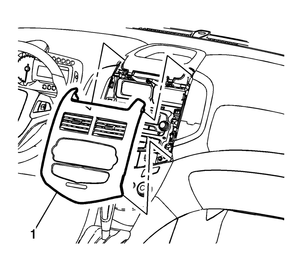
- Using a flat bladed plastic trim tool, release the retainers securing the center molding?€‰(1) to the instrument panel assembly.
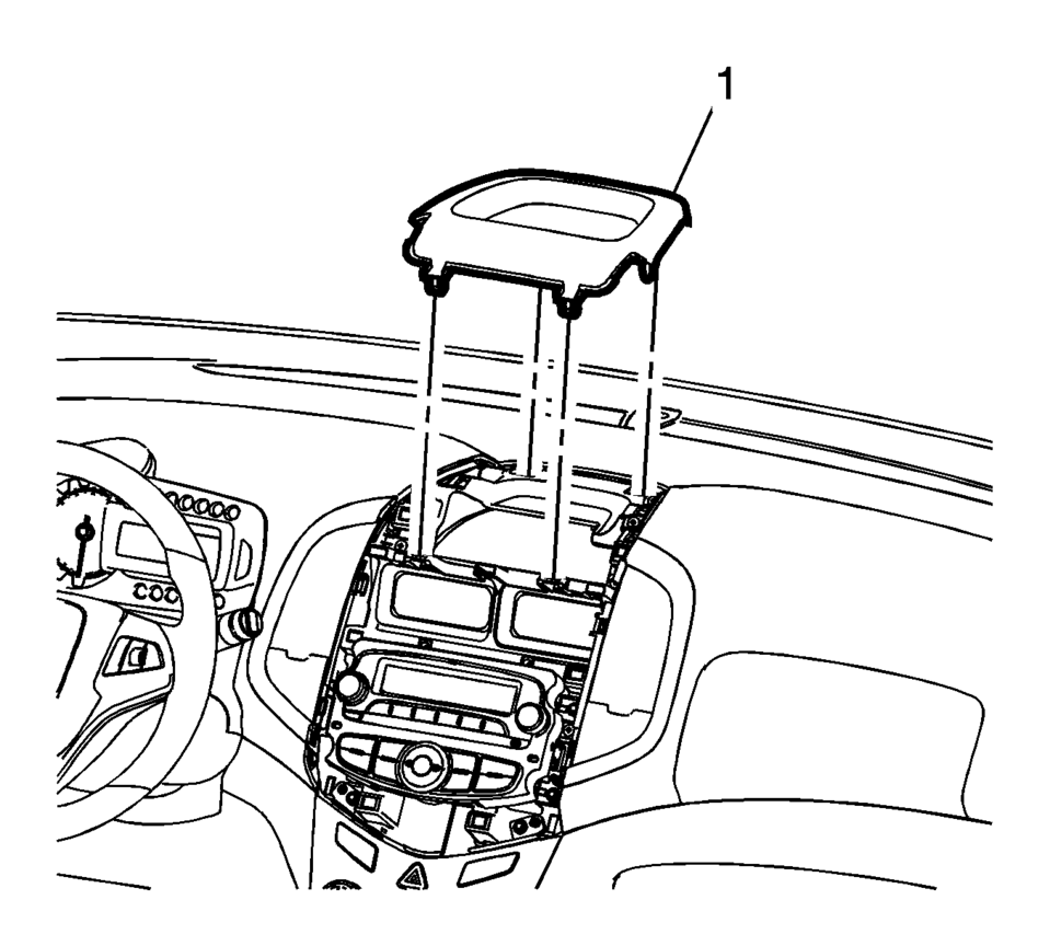
- Using a flat bladed plastic trim tool, disengage the retainers securing the center upper trim molding?€‰(1) to the instrument panel assembly.
- Disconnect electrical connections.
- Apply the parking brake.
- Move the shifter from ?€?Park?€? to the ?€?Neutral?€? position.
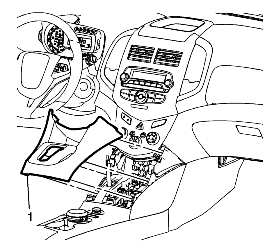
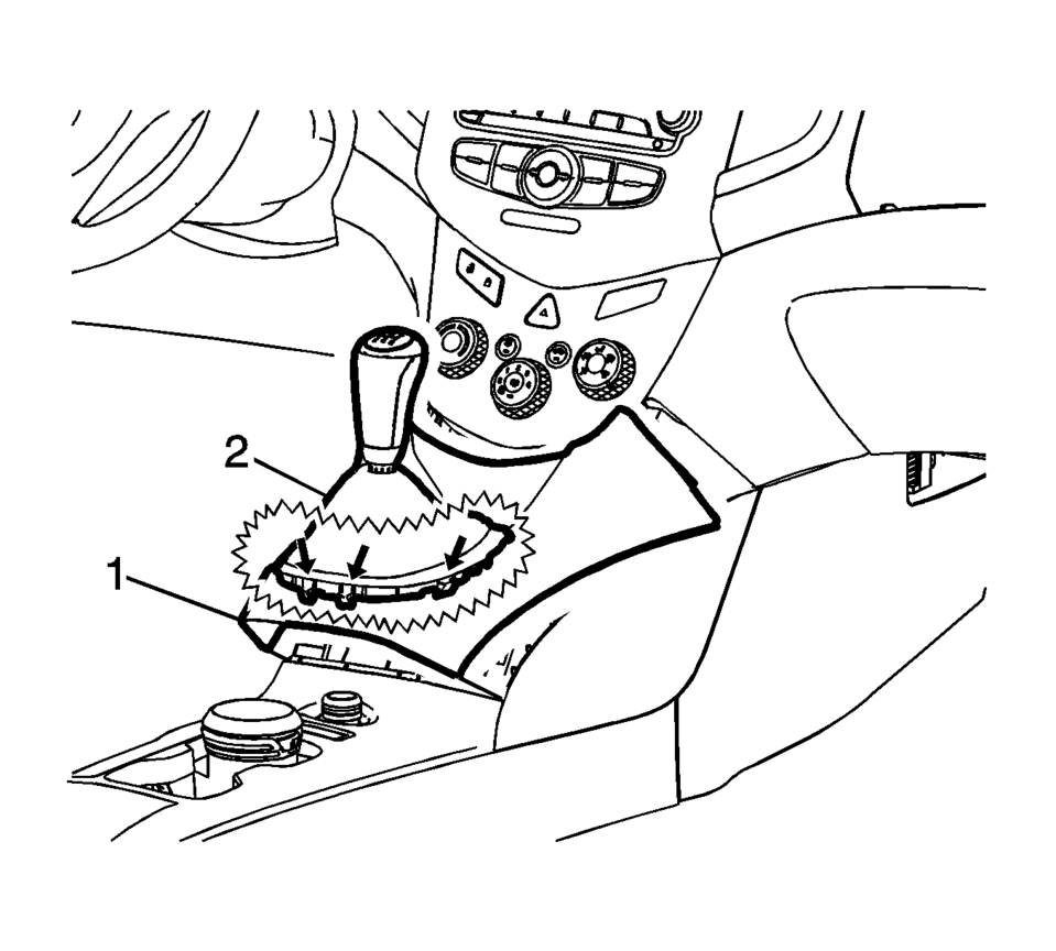
- Using a flat bladed plastic trim tool, release the retainers securing the console cover?€‰(1) to the console assembly.
- Disconnect electrical connections.
- Using a flat bladed plastic trim tool, release the retainers securing the console cover?€‰(1) to the console assembly.
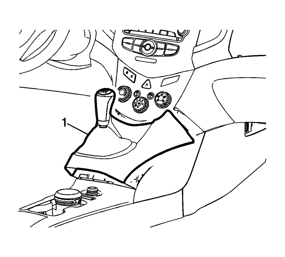
- Reach under the console cover assembly?€‰(1) and release the retainer tabs securing the transmission shift lever boot?€‰(2) to the console cover assembly.
- Feed the transmission control lever boot assembly through the opening in the console cover assembly?€‰(1).
- Remove the console cover assembly?€‰(1) from the vehicle.
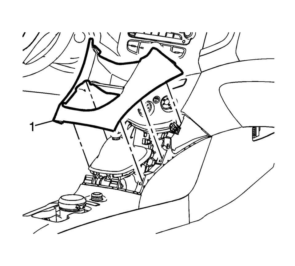
- Remove the heater and air conditioning control retainers?€‰(1).
- Disconnect the electrical connectors from the switches.
- Disconnect the heater and air conditioning temperature control cable.
- Disconnect the mode control cable.
- Disconnect the connectors of HVAC control ?€“ J1 (Blower), J2 (Main) and J3 (HVAC Module).
- Remove the heater and air conditioning control from the HVAC bezel?€‰(2) by removing the four screws.
- Remove the electrical switches from the HVAC bezel.
Note:
Steps 4 to 7 are for vehicles equipped with Automatic Transmission only.
Note:
Steps 8 to 11 are for vehicles equipped with Manual Transmission only.
- Instrument Panel Trim Installation Procedure
-
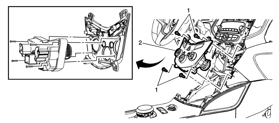
- Install the heater and air conditioning control to the supplied HVAC
bezel?€‰(2) by installing the four screws.
Tighent
Tighten the four screws to 5.5 Nm (49?€‰lb?€‰in). - Install the removed electrical switches to the supplied HVAC bezel.
- Connect the connectors of HVAC control ?€“ J1 (Blower), J2 (Main) and J3 (HVAC Module).
- Connect the mode control cable.
- Connect the heater and air conditioning temperature control cable.
- Connect the electrical switch connectors.
- Install the HVAC control assembly with bezel?€‰(2) to the instrument panel and secure with the retainers?€‰(1).
- Position the console cover assembly?€‰(1) to the console assembly.
- Feed the transmission control lever boot assembly through the opening in the console cover assembly?€‰(1).
- Snap the transmission control lever boot assembly?€‰(2) to the console cover?€‰(1) ensuring the retainer tabs lock the boot assembly to the cover.
- Install the cover assembly to the vehicle.
- Connect the electrical connections.
- Install the front floor console cover.
- Connect the electrical connections to the supplied center upper trim molding?€‰(1).
- Install the center upper trim molding to the instrument panel ensuring that the retainers are fully engaged.
- Install the supplied center molding?€‰(1) to the instrument panel ensuring that the retainers are fully engaged.
Note:
Steps 7 to 10 are for vehicles equipped with Manual Transmission only.
Note:
Steps 11 and 12 are for vehicles equipped with Automatic Transmission only.
- Install the heater and air conditioning control to the supplied HVAC
bezel?€‰(2) by installing the four screws.
- Front Door Trim Removal Procedure
-
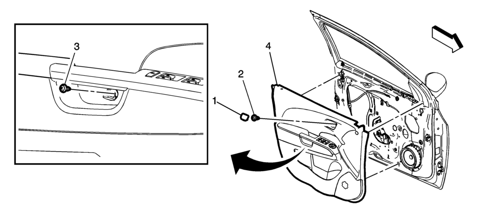
- Using an appropriate plastic trim tool, remove the front side door upper front trim panel?€‰(1).
- Remove the front side door inside handle bolt finish cap?€‰(1).
- Remove the front side door inside handle fastener?€‰(2).
- Remove the front side door trim fastener?€‰(3).
- Use the appropriate plastic trim tool to aid in the removal of the front door trim?€‰(4).
- Pull upwards on the door lock retainer cable to disengage.
- Disconnect the electrical connector.
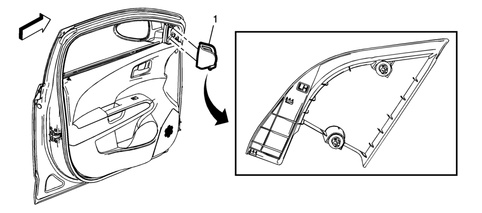
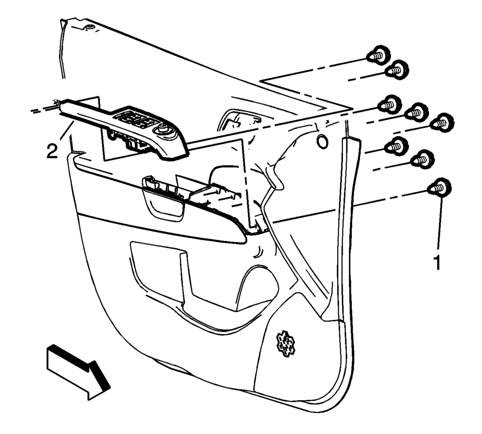
- Remove the front side door window switch bezel screw?€‰(1) (Qty:8).
- Remove the front side door window switch bezel assembly?€‰(2).
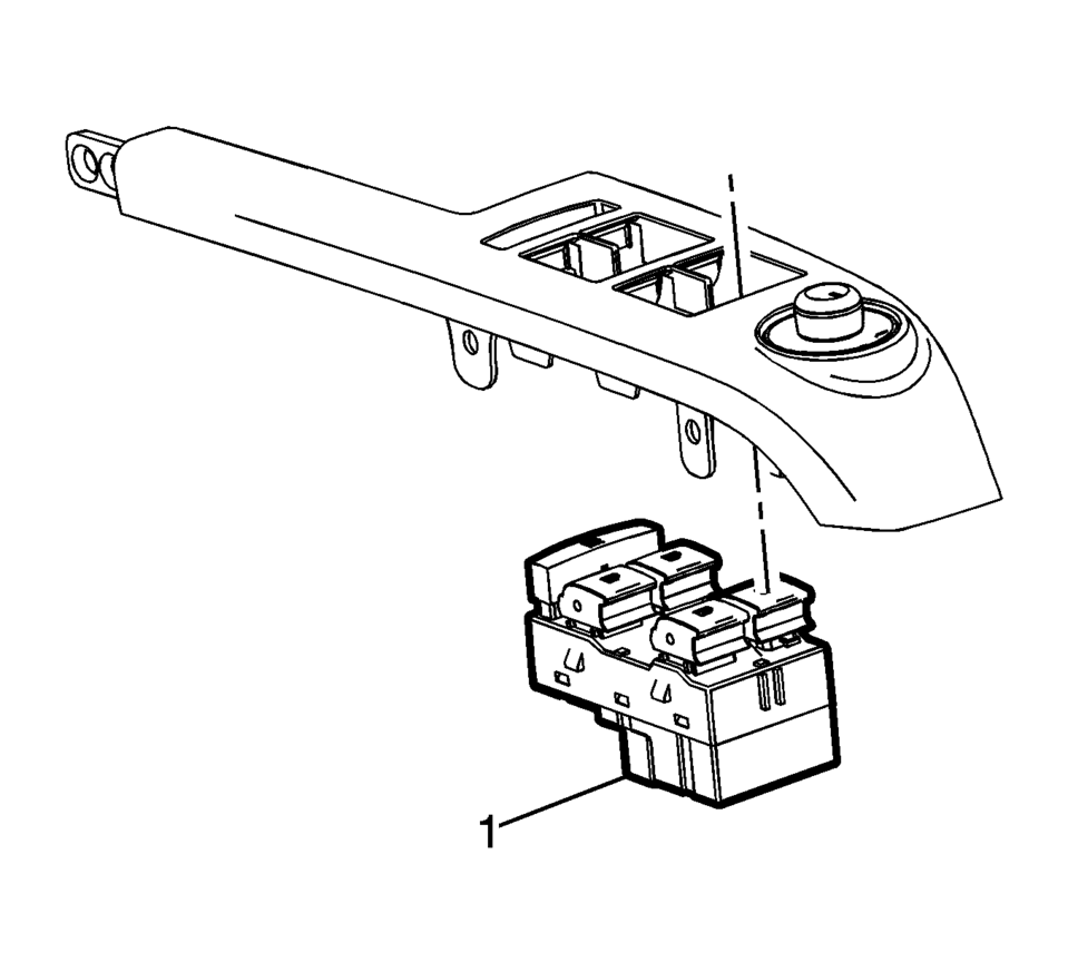
- Disconnect the retainers and remove the front side door window switch assembly?€‰(1).
- Disconnect the electrical connectors.
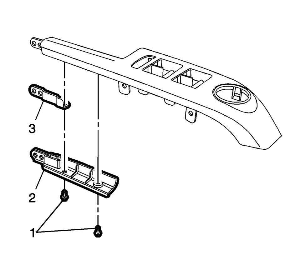
- Remove the front side door window switch bezel bracket screws?€‰(1).
- Remove the front side door window switch bezel brackets?€‰(2), (3).
Note:
Bezel brackets and screws are to be reused.
- Front Door Trim Installation Procedure
-
- Install the front side door window switch bezel brackets?€‰(2), (3) to the supplied front side door window switch bezel and secure with the screws?€‰(1).
- Connect the electrical connectors.
- Install the front side front door window switch assembly?€‰(1) to the supplied front side door window switch bezel.
- Install the front side door window switch bezel assembly?€‰(2) to the front door trim panel.
- Secure the front door window switch bezel assembly with the screws?€‰(1) (Qty:8).
- Connect the electrical connections.
- Install the front door trim panel?€‰(4) to the front door.
- Install the front side door trim fastener?€‰(3).
- Install the front side door inside handle fastener?€‰(2).
- Install the front side door inside handle bolt finish cap?€‰(1).
- Install the front side door upper front trim panel?€‰(1).
 Instrument Cluster Upper Bezel Replacement
Instrument Cluster Upper Bezel Replacement
Callout
Component Name
1
Instrument Panel Cluster Upper Bezel
Procedures
...
 Instrument Panel Accessory Upper Trim Plate Replacement
Instrument Panel Accessory Upper Trim Plate Replacement
Callout
Component Name
Preliminary Procedure
Remove the instrument pane ...
Other materials:
Steering Column Replacement
Removal Procedure
Caution: With wheels of the vehicle facing straight ahead,
secure the steering wheel utilizing steering column anti-rotation pin,
steering column lock, or a strap to prevent rotation. Locking of the
steering column will prevent damage and a possible ...
Instrument Panel Outer Air Outlet Replacement - Right Side
Instrument Panel Outer Air Outlet Replacement - Right Side
Callout
Component Name
Preliminary Procedure
Remove the right instrument panel upper trim panel. Refer to Instrument
Panel Upper Trim Panel Replacement - Right Side ...
Intake Manifold Replacement (LDE)
Removal Procedure
Disconnect the negative battery cable. Refer to Battery Negative Cable
Disconnection and Connection.
Remove the throttle body assembly. Refer to Throttle Body Assembly Replacement.
Disconnect wiring harness plug.
Disconnect the pipes from ...

0.0061