Chevrolet Sonic Repair Manual: Neutral - Engine Running (Gen 1)
When the gear selector is moved to the Neutral (N) position, the hydraulic and electrical system operation is identical to Park (P) range. However, if Neutral is selected after the vehicle was operating in Reverse (R), the normally-high 35R pressure control solenoid 2 is commanded OFF and the following changes would occur in the hydraulic system.
- 3-5 Reverse Clutch Releases
-
Manual Valve
The manual valve is moved to the Neutral position and blocks line pressure from entering the reverse fluid circuit. Reverse fluid, from the 3-5-reverse clutch regulator valve and the clutch select valve, is opened to an exhaust passage at the manual valve.
35R Pressure Control Solenoid 2
The 35R PC solenoid 2 is commanded OFF allowing PCS 35 reverse clutch fluid from the 3-5-reverse clutch regulator valve to exhaust.
3-5-Reverse Clutch Regulator Valve
PCS 35 reverse clutch fluid exhausts, allowing 3-5-reverse clutch regulator valve spring force to move the 3-5-reverse clutch regulator valve to the released position. This allows 35 reverse clutch fluid pressure to exhaust into the compensator feed circuit in order to assist the 3-5-reverse clutch piston spring to quickly release the 3-5-reverse clutch.
3-5-Reverse Clutch
3-5-reverse clutch spring force, assisted by compensator feed pressure, moves the 3-5-reverse clutch piston to release the 3-5-reverse clutch plates and force 35 reverse clutch fluid to exhaust from the 3-5-reverse and 4-5-6 clutch housing assembly. The exhausting 35 reverse clutch fluid pressure is routed to the 3-5-reverse clutch regulator valve where it enters the 35 reverse clutch feed/compensator feed circuit.
Clutch Select Valve
When reverse fluid exhausts from the default override shuttle valve, shift solenoid fluid continues to hold the clutch select valve against clutch select valve spring force allowing 35 reverse clutch feed fluid to exhaust into the reverse circuit.
- Neutral?EEngine Running
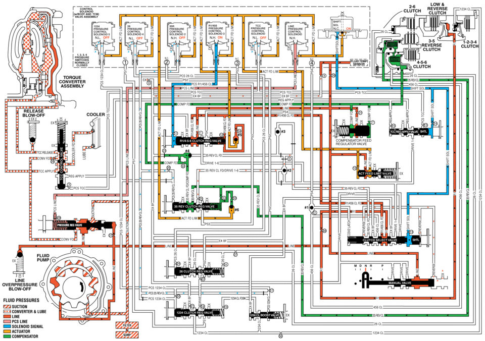
low mc reverse clutch solenoid solenoid n.h or; nh on nl 3-5 reverse clutch clutch 4-5-6 clutch tofioue converter assembly release cooler compensator feed regulator valve pcs mc pcs35 revcl unvfd tddapp -lwe fluid pressures suction converter lube line pcs line solenoid actuator compensatdr _1234 cl cl
 Lubrication Description
Oil is applied under pressure to the crankshaft (8), connecting rods (5), camshaft
adjuster (1), camshaft bearing surfaces (3) and valve tappets (4). All other movi ...
 Neutral - Engine Running (Gen 2)
When the gear selector is moved to the Neutral (N) position, the hydraulic and
electrical system operation is identical to Park (P) range. However, if Neutral
is selected after the vehicle was ope ...
Other materials:
Front Side Door Lock Cylinder Coding (Free Wheeling)
Special Tools
BO-49753 Assembly Tool
The door lock cylinder uses 8 of the 8?€‰cut positions. The tumbler positions
are staggered from side to side, 4 on one side and 4 on the other, are not self-retaining,
and are not snap in.
Note: All lock cylinders for side milled keys ha ...
Liftgate Emblem/Nameplate Replacement (Hatchback)
Liftgate Emblem/Nameplate Replacement
Callout
Component Name
1
Liftgate Emblem/Nameplate Assembly
Caution: Refer to Exterior Trim Emblem Removal Caution.
Procedure
The part and surface should be 2 ...
Air Conditioning O-Ring Seal Replacement
Removal Procedure
Disassemble the A/C refrigerant components. Refer to the appropriate
repair procedure
Note: Cap or tape the open A/C refrigerant components immediately
to prevent system contamination.
Cap or tape the A/C refrigerant components.
...

0.0094