Chevrolet Sonic Repair Manual: Steering Linkage Inner Tie Rod Inspection
Special Tools
GE-8001 Dial Indicator Set
For equivalent regional tools, refer to Special Tools.
- Turn the ignition key to the ON position with the engine OFF.
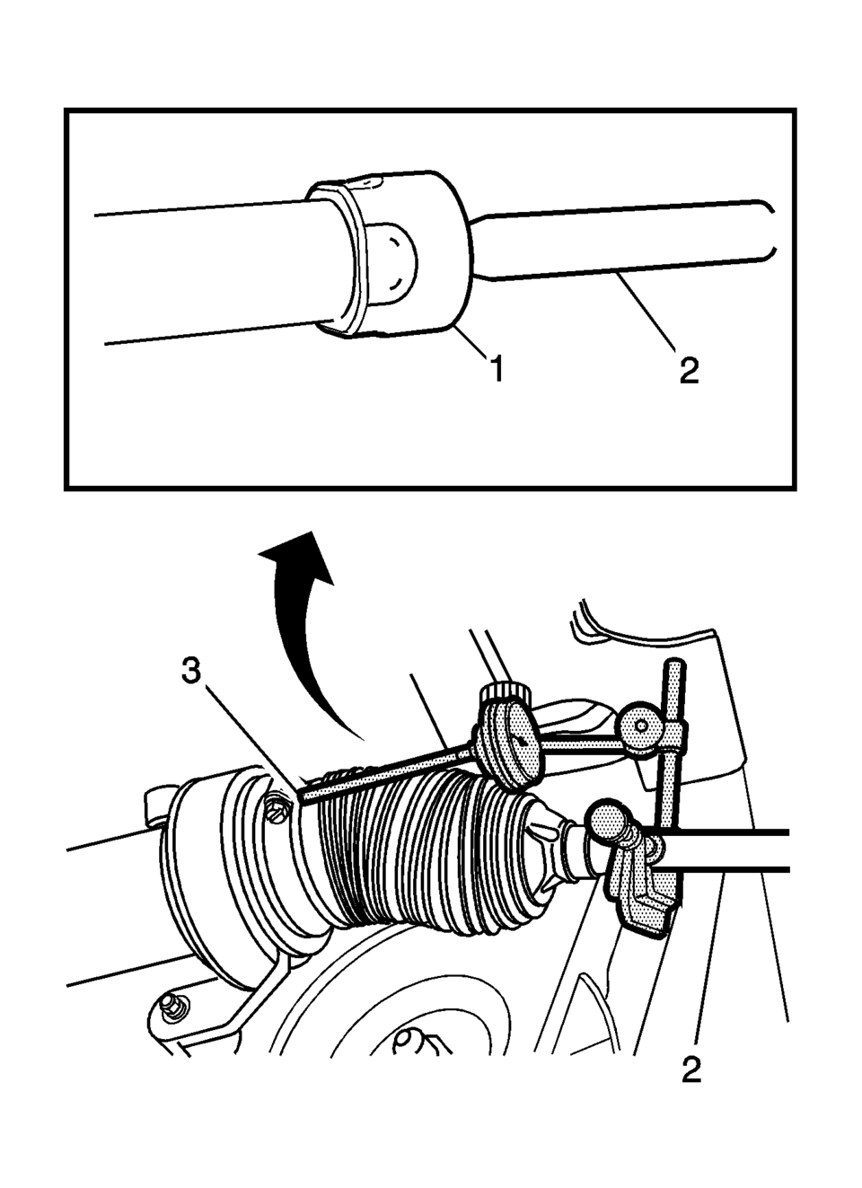
- With the aid of an assistant, turn the steering wheel to the full stop position and hold the steering wheel in that position until the test is complete. Part of the steering linkage inner tie rod (2) being tested should be inside the steering gear housing. The inner tie rod housing (1) being tested should be inside the steering gear housing and seated against the steering stop.
- Raise and support the vehicle. Refer to Lifting and Jacking the Vehicle.
- If there is not a good location for the GE-8001 dial indicator pointer at the steering gear housing, install a large worm gear hose clamp (3) to the steering gear housing over the larger steering gear boot clamp and align the clamp so that the screw can be a location for the GE-8001 dial indicator pointer.
- Install the GE-8001 dial indicator between the inner tie rod and the steering gear housing or the worm gear clamp in such a way as to measure the lash between the inner tie rod and the steering gear housing. The lash between the inner tie rod and the steering gear housing is equal to the lash between the inner tie rod and the inner tie rod housing because the inner tie rod housing is inside the steering gear housing during this procedure.
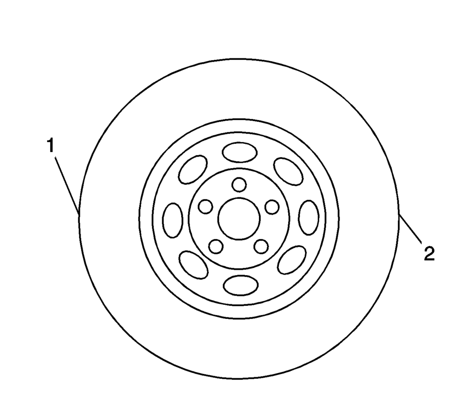
- Grasping the tire at the 3 o'clock (2) and 9 o'clock (1) positions, gently push in on one side of the tire in order to remove any lash.
- Zero the GE-8001 dial indicator .
- On the same side of the tire previously pushed in, gently pull out and measure the lash.
- Record the measurement shown on the GE-8001 dial indicator .
- If the measured value exceeds 0.5 mm (0.02 in), replace the inner tie rod. Refer to Steering Linkage Inner Tie Rod Replacement.
- Repeat the procedure for the other side.
Note:
This inspection procedure does not supersede local government required inspections that have more stringent requirements.
Note:
Only move the tire enough to feel any lash between the inner tie rod and the inner tie rod housing without moving the steering gear rack.
 Instrument Panel Tie Bar Replacement
Removal Procedure
Remove the Instrument panel assembly. Refer to Instrument Panel Assembly
Replacement.
Remove the steering column and wheel from the vehicle. Refer to Steering
...
 Steering Linkage Inner Tie Rod Replacement
Steering Linkage Inner Tie Rod Replacement
Callout
Component Name
Preliminary Procedures
Raise and support the vehicle. Refer to Li ...
Other materials:
Safety Function Override
If the battery on the vehicle has been recharged or disconnected, or is not working,
the windows will need to be reprogrammed for the express-up feature to work. Before
reprogramming, replace or recharge the vehicle's battery.
To program the driver window:
1. With the ignition in ACC/ ACCE ...
Tire Pressure Monitor Operation
This vehicle may have a Tire Pressure Monitor System (TPMS). The TPMS is designed
to warn the driver when a low tire pressure condition exists. TPMS sensors are mounted
onto each tire and wheel assembly, excluding the spare tire and wheel assembly.
The TPMS sensors monitor the air pressure in ...
Automatic Transmission Shift Lock Control Function Check
Warning: When you are doing this inspection, the vehicle could move
suddenly. If the vehicle moves, you or others could be injured.
Before starting this check, be sure there is enough room
around the vehicle. It should be parked on a level surface.
Apply the parking brake. Be read ...

0.0079