Chevrolet Sonic Repair Manual: Blower Motor Replacement
- Removal Procedure â Production Blower Motor
-
- Remove the passenger side instrument panel insulator. Refer to Instrument Panel Insulator Replacement.
- Remove the passenger side inflatable restraint instrument panel lower module. Refer to Instrument Panel Lower Airbag Replacement - Passenger Side.
- Remove the right side floor heater duct. Refer to Floor Air Outlet Duct Replacement - Right Side.
- Remove the 3 blower motor cover screws, and remove the blower motor cover.
- Disconnect the blower motor wire harness connector.
- Cut out the blower motor assembly using a utility knife, following the narrow groove around the blower motor assembly in the lower case.
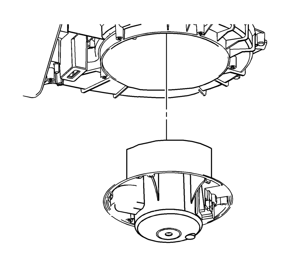
- Remove the blower motor assembly.
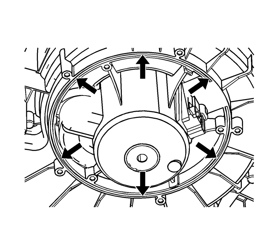
Note:
The blower motor is molded into heater and air conditioning evaporator and blower lower module case during the manufacturing process, therefore heater and air conditioning evaporator and blower lower module case must be cut to remove blower motor assembly. Cut through the case as straight as possible because the blower motor cup must be reused. In order to prevent damage to the component, do not cut any deeper than necessary to remove the blower motor cup.
- Removal Procedure - Service Blower Motor
-
- Remove the passenger side instrument panel insulator. Refer to Instrument Panel Insulator Replacement.
- Remove the passenger side inflatable restraint instrument panel lower module. Refer to Instrument Panel Lower Airbag Replacement - Passenger Side.
- Remove the right side floor heater duct. Refer to Floor Air Outlet Duct Replacement - Right Side.
- Remove the blower motor cover (if required).
- Disconnect the blower motor wire harness connector.
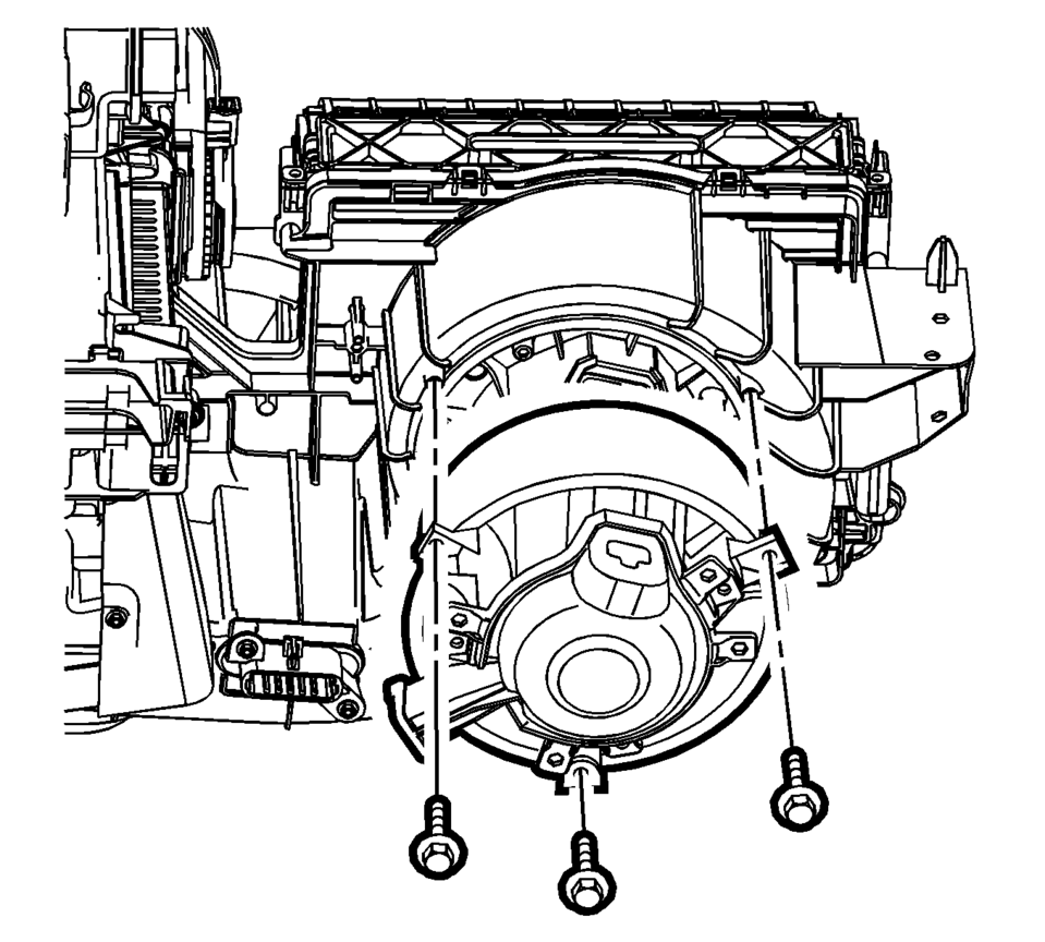
- Remove the 3 outer most screws from blower motor service ring, or blower integrated ring.
- Remove the blower motor assembly.
- Installation Procedure
-
- Clean and smooth the rough edges, and remove any burs of plastic from heater and air conditioning evaporator and blower lower module case, where the original blower motor assembly was cut out of the heater and air conditioning evaporator and blower lower module case.
- Attach the blower motor service ring to the blower motor assembly using the service screws.
- When using the original blower motor assembly that has been cut out of the lower case, install the blower motor assembly with the service ring assembly to the heater and air conditioning evaporator and blower module lower case, with the additional service screws, and tighten the screws.
- When using the service blower motor kit, install the service blower motor assembly to the heater and air conditioning evaporator and blower lower module case, with additional service screws, and tighten the screws.
- Install the blower motor cover.
- Connect the blower motor wire harness connector.
- Install the right side floor heater duct. Refer to Floor Air Outlet Duct Replacement - Right Side.
- Install the passenger side inflatable restraint instrument panel lower module. Refer to Instrument Panel Lower Airbag Replacement - Passenger Side.
- Install the passenger side instrument panel insulator. Refer to Instrument Panel Insulator Replacement.
Caution:
Refer to Fastener Caution.
 Blower Motor
...
 Heater and Air Conditioning Evaporator and Blower Module Removal and Installation
Heater and Air Conditioning Evaporator and Blower Module Removal and
Installation
Callout
Component Name
Preliminary Procedures
...
Other materials:
Door Locks
Warning
Unlocked doors can be dangerous.
Passengers, especially children, can easily open the doors and fall out
of a moving vehicle. When a door is locked, the handle will not open it. The
chance of being thrown out of the vehicle in a crash is increased if the doors
are not locked. S ...
Reporting Safety Defects to the United States Government
If you believe that your vehicle has a defect which could cause a crash or could
cause injury or death, you should immediately inform the National Highway Traffic
Safety Administration (NHTSA) in addition to notifying General Motors.
If NHTSA receives similar complaints, it may open an investig ...
OnStar Description and Operation
This OnStarÂź system consists of the following components:
Telematics communication interface control module
OnStarÂź three button assembly
Microphone
Cellular antenna
Navigation antenna
BluetoothÂź antenna (If equipped)
Back up battery (If equipped)
This system also interfaces wi ...

0.0055