Chevrolet Sonic Repair Manual: Brake Pedal Assembly Replacement
- Removal Procedure
-
- Remove the battery tray. Refer to Battery Tray Replacement.
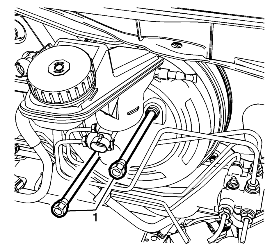
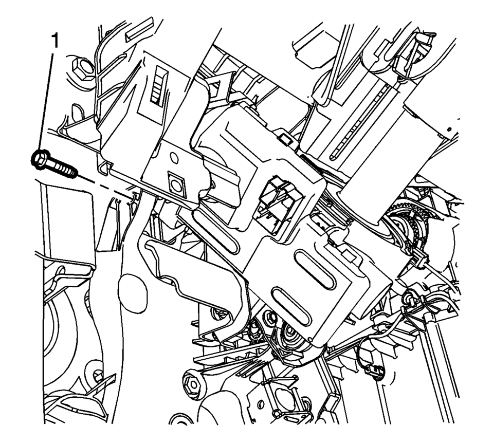
- Remove the power vacuum brake booster bolts (1).
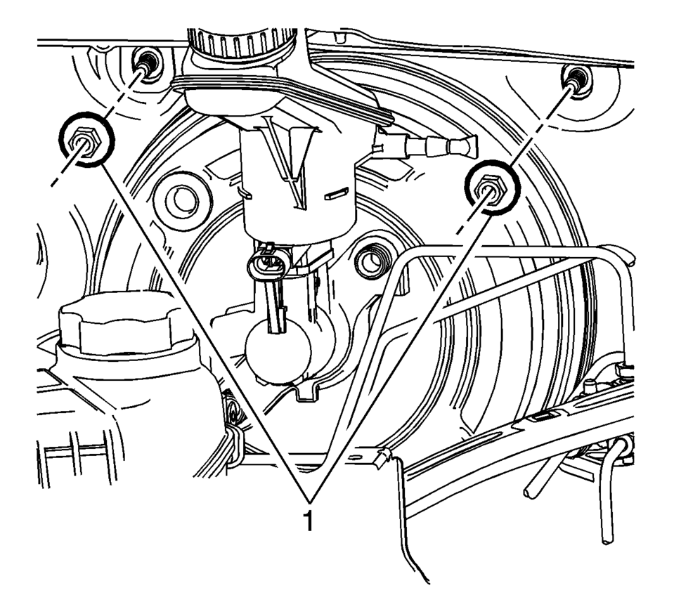
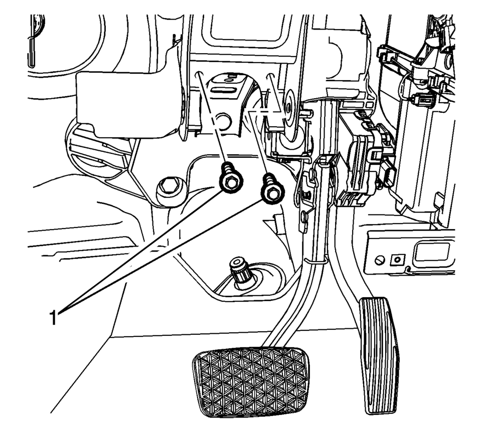
- Remove the brake pedal assembly upper nuts (1)
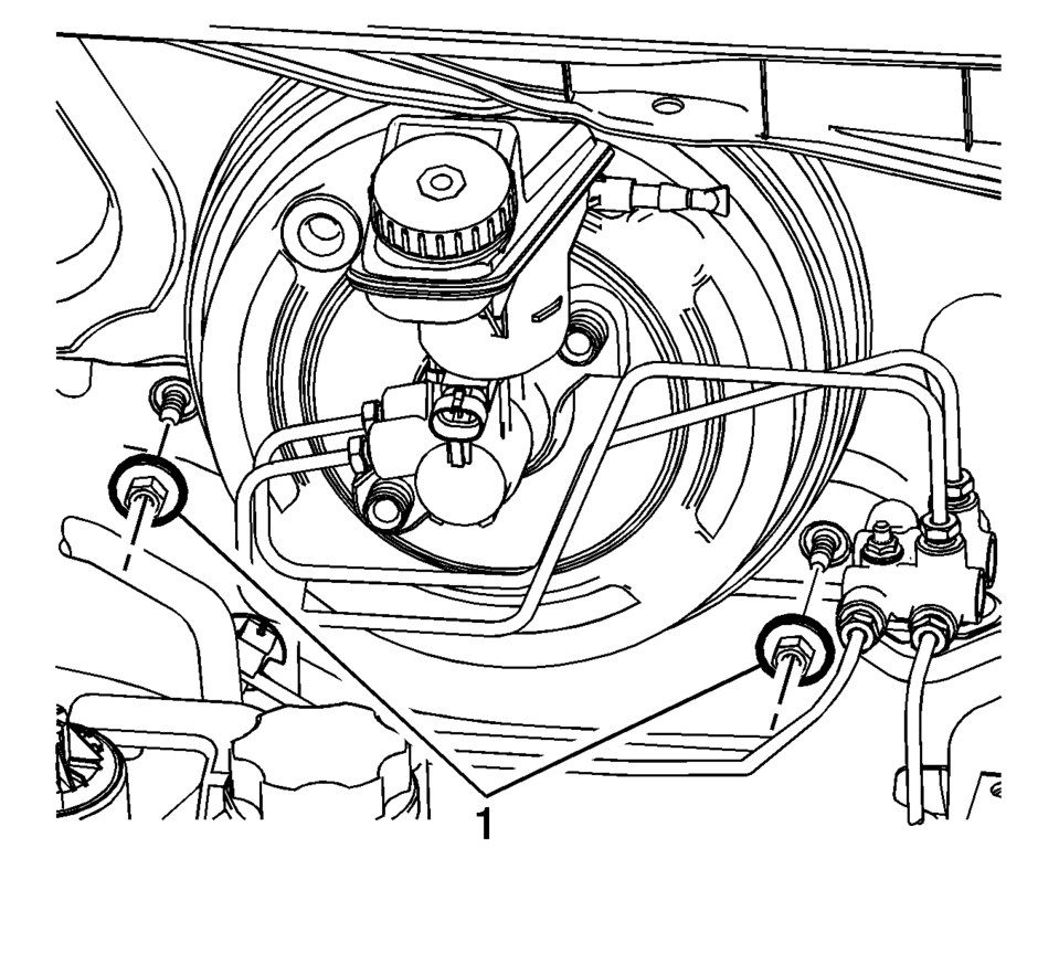
- Remove the brake pedal assembly lower nuts (1)
- Remove the steering column. Refer to Steering Column Replacement.
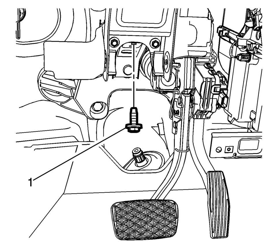
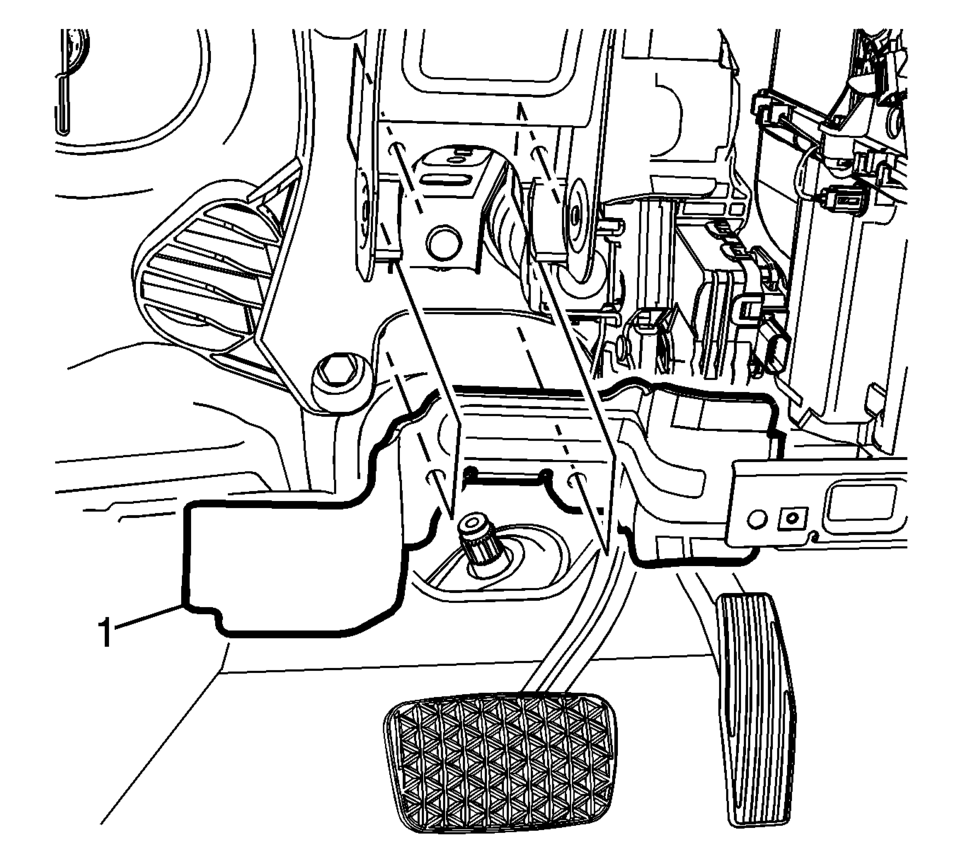
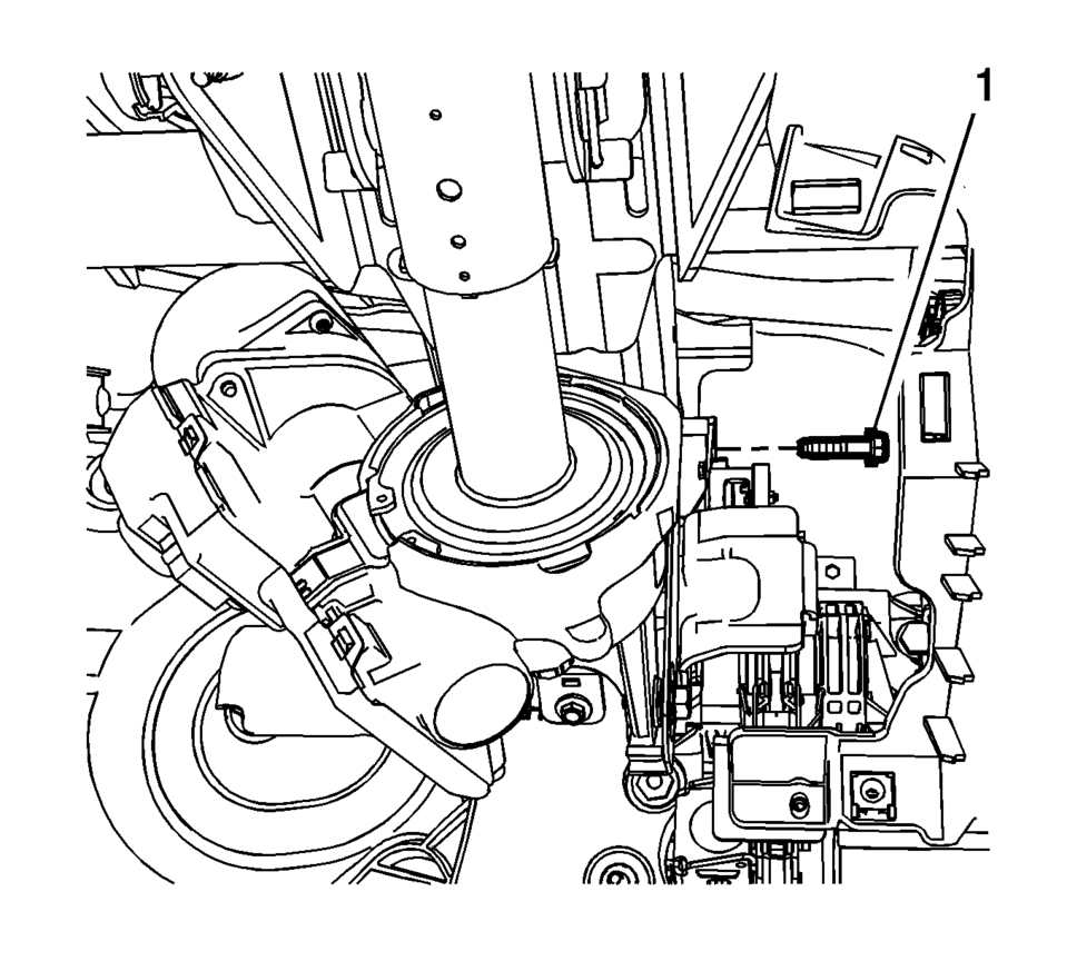
- Remove the brake pedal release bracket bolt (1).
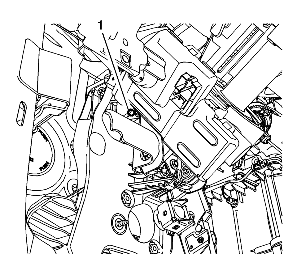
- Remove the brake pedal release bracket bolts (1).
- Remove the brake pedal release bracket (1).
- Disconnect the brake pedal position sensor electrical connector.
- On manual transmission equipped vehicles, disconnect the clutch pedal position sensor electrical connector.
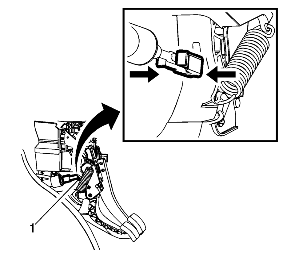
- On manual transmission equipped vehicles, disconnect the clutch master cylinder pushrod retainer (1). Refer to Clutch Master Cylinder Replacement
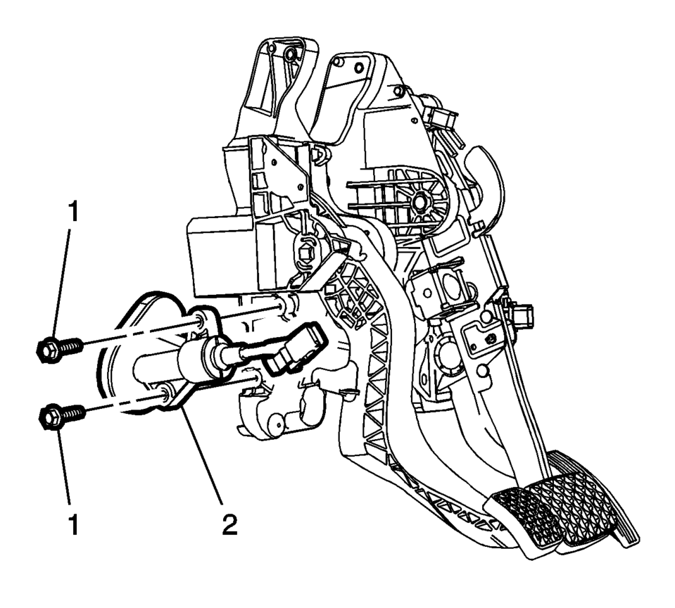
- On manual transmission equipped vehicles, remove the clutch master cylinder bolts (1) and position aside the clutch master cylinder (2) without disconnecting the clutch fluid pipe. Clutch Master Cylinder Replacement
- Position aside any wiring harnesses attached to the brake pedal assembly bracket, as necessary.
- Remove the left upper brake pedal assembly bolt (1).
- Remove the right upper brake pedal assembly bolt (1).
- Using a suitable tool, carefully cut off the 2 upper brake pedal assembly locating pins (1).
- Remove the brake pedal assembly from the vehicle.
- Remove any necessary components from the brake pedal assembly.
- Installation Procedure
-
- Using a suitable tool, carefully cut off the 2 upper brake pedal assembly locating pins.
- Install any removed components from the brake pedal assembly.
- Install the brake pedal assembly to the vehicle.
- Install the brake pedal assembly lower nuts (1) and tighten to 19 Y
(14 lb ft)
.
- Install the brake pedal assembly upper nuts (1) and tighten to 19 Y
(14 lb ft)
.
- Install the right upper brake pedal assembly bolt (1) and tighten to
9 Y (80 lb in)
.
- Install the left upper brake pedal assembly bolt (1) and tighten to
9 Y (80 lb in)
.
- Reposition any wiring harnesses attached to the brake pedal assembly bracket, as necessary.
- On manual transmission equipped vehicles, install the clutch master cylinder bolts (1) and the clutch master cylinder (2). Refer to Clutch Master Cylinder Replacement.
- On manual transmission equipped vehicles, connect the clutch master cylinder pushrod retainer (1). Refer to Clutch Master Cylinder Replacement.
- On manual transmission equipped vehicles, connect the clutch pedal position sensor electrical connector.
- Install the brake pedal release bracket (1).
- Install the brake pedal release bracket bolts (1) and tighten to
22 Y (16 lb ft)
.
- Install the brake pedal release bracket bolt (1) and tighten to
22 Y (16 lb ft)
.
- Connect the brake pedal position sensor electrical connector.
- Install the steering column. Refer to Steering Column Replacement.
- Install the power vacuum brake booster bolts (1) and tighten to
19 Y (14 lb ft)
.
- Install the battery tray. Refer to Battery Tray Replacement.
Caution:
Refer to Fastener Caution.
Caution:
Refer to Fastener Caution.
 Front Brake Hose Replacement
Removal Procedure
Warning: Refer to Brake Dust Warning.
Warning: Refer to Brake Fluid Irritant Warning.
Danger: Do not use a service jack to lift this vehicle. Li ...
 Brake Pedal Position Sensor Calibration
Calibration Criteria
Note: Do not apply the brake pedal during the brake pedal position
sensor calibration procedure. Any movement of the brake pedal during this
procedure will ca ...
Other materials:
Scheduling Service Appointments
When the vehicle requires warranty service, contact your dealer and request an
appointment. By scheduling a service appointment and advising the service consultant
of your transportation needs, your dealer can help minimize your inconvenience.
If the vehicle cannot be scheduled into the service ...
Hood Primary and Secondary Latch Replacement
Hood Primary and Secondary Latch Replacement
Callout
Component Name
1
Hood Primary and Secondary Latch Bolt (Qty:?€‰2)
Caution: Refer to Fastener Caution.
Tighten
22?€‰Y (16?€‰lb?€‰ft) ...
Instrument Panel Upper Trim Panel Replacement - Right Side
Instrument Panel Upper Trim Panel Replacement - Right Side
Callout
Component Name
Preliminary Procedure
Disable the SIR system. Refer to SIR Disabling and Enabling.
Remove the instrument panel center molding. Refer to Inst ...

0.0055