Chevrolet Sonic Repair Manual: Camshaft Actuator System Description
- Camshaft Actuator System Overview
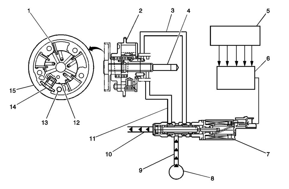
(1) Camshaft Actuator Vane (2) Timing Chain Sprocket (3) Engine Oil Pressure-For retarding the camshaft (4) Camshaft (5) Input Signals from Engine Sensors (6) Engine Control Module (ECM) (7) Camshaft Actuator Solenoid (8) Engine Oil Pump (9) Engine Oil Pressure Supply (10) Engine Oil Drain (11) Engine Oil Pressure-For advancing the camshaft (12) Camshaft Actuator Rotor (13) Camshaft Position Sensor Reluctor (14) Camshaft Actuator Lock Pin (15) Camshaft Actuator Housing
The camshaft actuator system enables the engine control module (ECM) to change camshaft timing of all 4 camshafts while the engine is operating. The camshaft position (CMP) actuator assembly (15) varies the camshaft position in response to directional changes in oil pressure. The CMP actuator solenoid valve controls the oil pressure that is applied to advance or retard a camshaft. Modifying camshaft timing under changing engine demand provides better balance between the following performance concerns:
- Engine power output
- Fuel economy
- Tailpipe emissions
The CMP actuator solenoid valve (7) is controlled by the ECM. The crankshaft position (CKP) sensor and the CMP sensors are used to monitor changes in camshaft positions. The ECM uses the following information in order to calculate the desired camshaft positions:
- Engine coolant temperature
- Calculated engine oil temperature (EOT)
- Mass air flow (MAF)
- Throttle position (TP)
- Vehicle speed
- Volumetric efficiency
- Operation
-
The CMP actuator assembly has an outer housing that is driven by an engine timing chain. Inside the assembly is a rotor with fixed vanes that is attached to the camshaft. Oil pressure that is applied to the fixed vanes will rotate a specific camshaft in relationship to the crankshaft. The movement of the intake camshafts will advance the intake valve timing. The movement of the exhaust camshafts will retard the exhaust valve timing. When oil pressure is applied to the return side of the vanes, the camshafts will return to 0 crankshaft degrees, or top dead center (TDC). The CMP actuator solenoid valve directs the oil flow that controls the camshaft movement. The ECM commands the CMP solenoid to move the solenoid plunger and spool valve until oil flows from the advance passage (11). Oil flowing thru the CMP actuator assembly from the CMP solenoid advance passage applies pressure to the advance side of the vanes in the CMP actuator assembly. When the camshaft position is retarded, the CMP actuator solenoid valve directs oil to flow into the CMP actuator assembly from the retard passage (3). The ECM can also command the CMP actuator solenoid valve to stop oil flow from both passages in order to hold the current camshaft position.
The ECM operates the CMP actuator solenoid valve by pulse width modulation (PWM) of the solenoid coil. The higher the PWM duty cycle, the larger the change in camshaft timing. The CMP actuator assembly also contains a lock pin (14) that prevents movement between the outer housing and the rotor vane assembly. The lock pin is released by oil pressure before any movement in the CMP actuator assembly takes place. The ECM is continuously comparing CMP sensor inputs with CKP sensor input in order to monitor camshaft position and detect any system malfunctions. If a condition exists in either the intake or exhaust camshaft actuator system, the opposite bank, intake or exhaust, camshaft actuator will default to 0 crankshaft degrees.
CMP Actuator System Operation Driving Condition
Change in Camshaft Position
Objective
Result
Idle
No Change
Minimize Valve Overlap
Stabilized Idle Speed
Light Engine Load
Retarded Valve Timing
Decrease Valve Overlap
Stabled Engine Output
Medium Engine Load
Advanced Valve Timing
Increase Valve Overlap
Better Fuel Economy with Lower Emissions
Low to Medium RPM with Heavy Load
Advanced Valve Timing
Advance Intake Valve Closing
Improved Low to Mid-range Torque
High RPM with Heavy Load
Retarded Valve Timing
Retard Intake Valve Closing
Improved Engine Output
 Camshaft
...
 Camshaft Cover Installation
Clean the sealing surfaces.
Note: The thickness of the sealing bead should be 2 mm (0.0787 in).
Apply sealing compound to areas (1) and (2). Refer ...
Other materials:
Rear Side Door Upper Front Auxiliary Weatherstrip Retainer Replacement
Rear Side Door Upper Front Auxiliary Weatherstrip Retainer Replacement
Callout
Component Name
1
Front Side Door Upper Front Auxiliary Weatherstrip Retainer (Qty:?€‰10)
Note: If the retainers are damaged when ...
Floor Air Outlet Duct Replacement - Left Side (LHD)
Floor Air Outlet Duct Replacement - Left Side
Callout
Component Name
Preliminary Procedure
Remove the instrument panel insulator, if equipped.
Remove the instrument panel lower trim pad cover. Refer to Instrument
Panel Low ...
Heated Oxygen Sensor Replacement - Sensor 2
Heated Oxygen Sensor Replacement - Sensor 2
Callout
Component Name
1
Heated Oxygen Sensor 2
Warning: In order to avoid being burned, do not service the
exhaust system while it is still hot. Service the ...

0.0069