Chevrolet Sonic Repair Manual: Clutch and Differential Housing Assemble
Special Tools
- R-0007761 Universal Handle for Pullers and Installers
- R-0407009 Countershaft Front Bearing Driver
- R-0407010 Input Shaft Needle Bearing Puller and Driver
- R-0407014 Gearshift Device Bushing Driver ?#8201;Use with R-0007761
- S-9707500 Axle Shaft Seal Installer
For equivalent regional tools, refer to Special Tools.
- Install the shift shaft bushings (3) using the R-0407014 bushing driver (2) and R-0007761 handle (1).
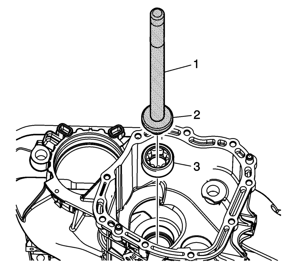
- Install the main shaft front bearing assembly (3) using the R-0407009 driver (2) and the R-0007761 handle (1).
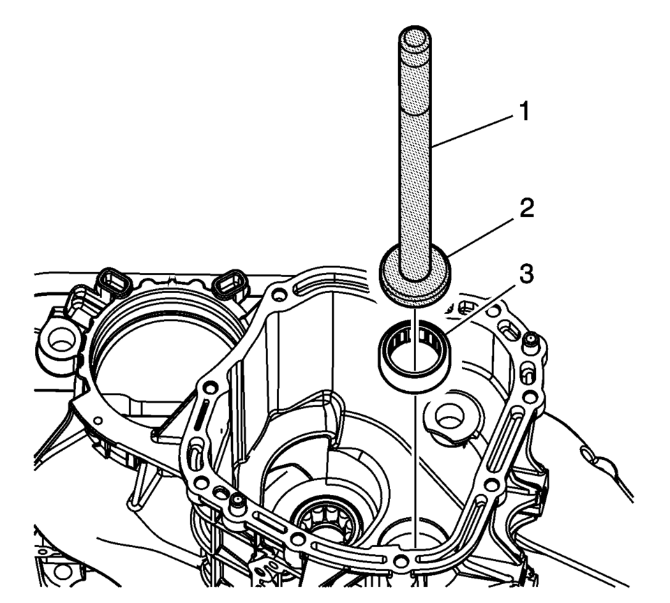
- Install the input shaft front bearing assembly (3) using the R-0407010 driver (2) and the R-0007761 handle (1).
- Install the clutch yoke shaft bushings (1).
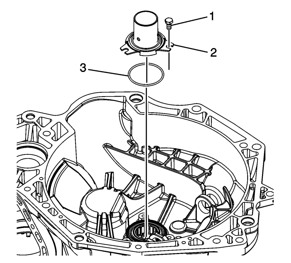
- Install the clutch release bearing collar seal (3).
- Install the clutch release bearing collar (2).
- Install the clutch release bearing collar bolt (1) and
tighten to 5 Y (44.3 lb in)
.
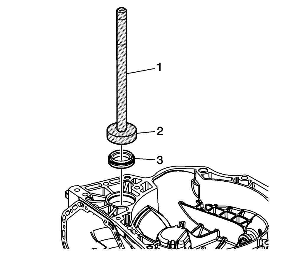
- Install the front wheel drive shaft oil seal assembly (3) using the S-9707500 seal installer (2) and the R-0007761 handle (1).
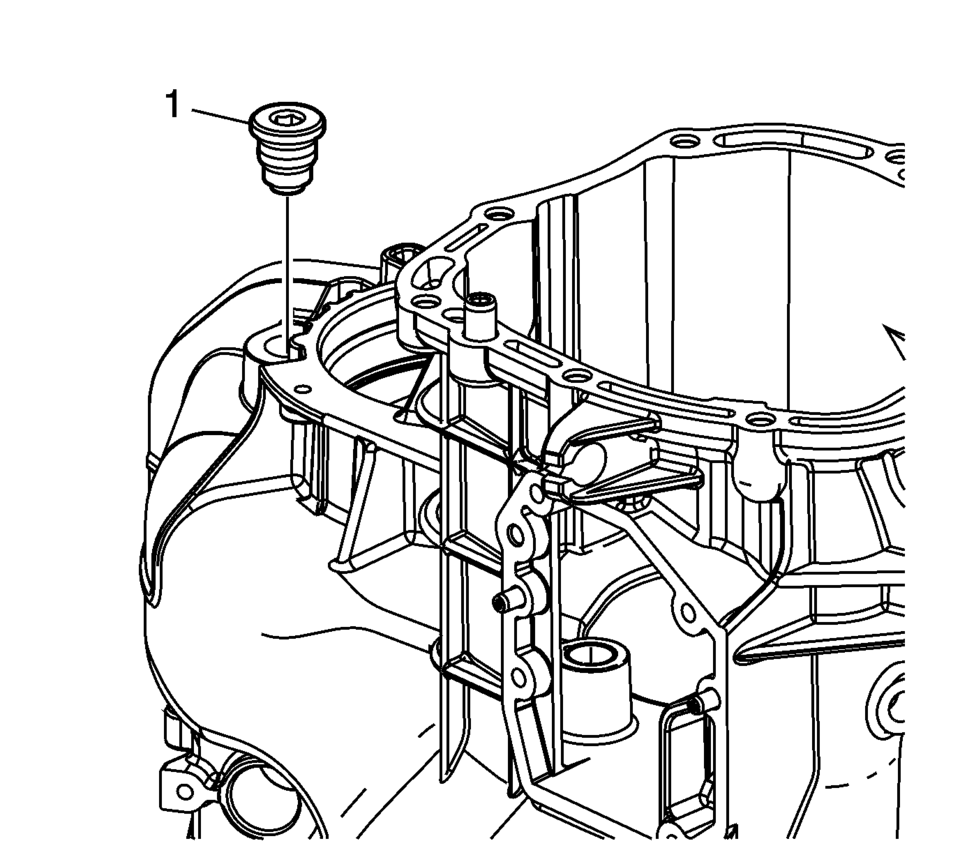
- Install the transmission magnet (1). Tighten to 4 Y
(35.4 lb in) plus 45? plus an additional 90?
.
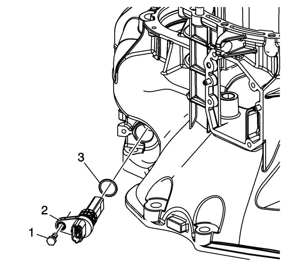
- Install the NEW vehicle speed sensor O-ring seal (3).
- Install the vehicle speed sensor assembly (2).
- Install the vehicle speed sensor bolt (1). Tighten to 5 Y
(44 lb in)
.
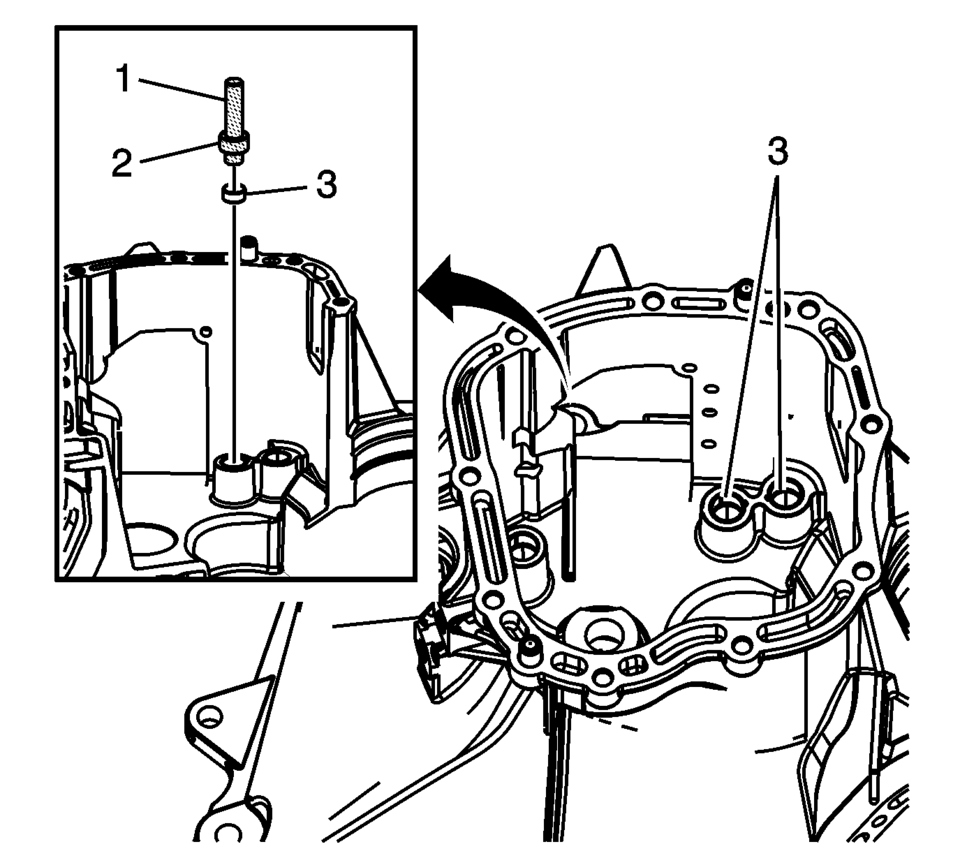
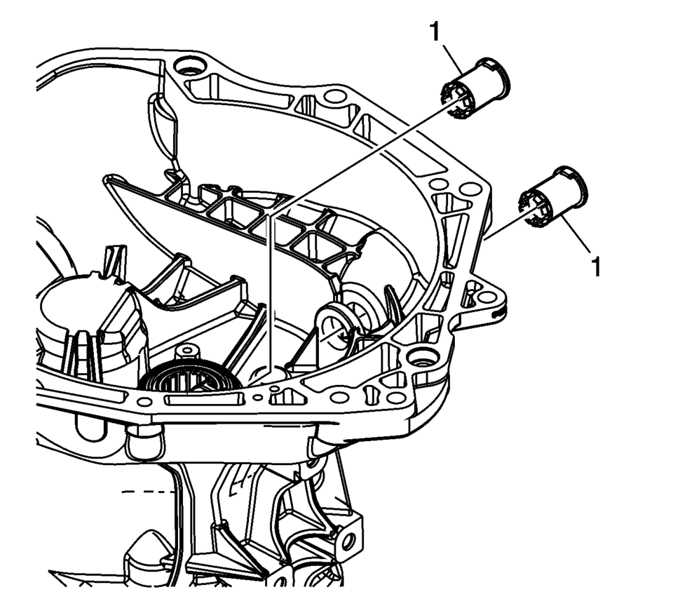
Note:
Align the tabs on the clutch yoke shaft bushings to the slots in the clutch and differential housing.
Caution:
Refer to Fastener Caution.
 Backup Lamp Switch Replacement
Backup Lamp Switch Replacement
Callout
Component Name
Preliminary Procedure
Disconnect the negative battery cable. Refer to
Bat ...
 Clutch and Differential Housing Cleaning and Inspection
Warning: Wear safety glasses to avoid injury when using compressed
air or any cleaning solvent. Bodily injury may occur if fumes are inhaled
or if skin is exposed to chemicals.
...
Other materials:
Brake System Warning Light
The vehicle brake system consists of two hydraulic circuits. If one circuit is
not working, the remaining circuit can still work to stop the vehicle. For normal
braking performance, both circuits need to be working
If the warning light comes on, there is a brake problem. Have the brake system
...
Rear Brake Rotor Replacement
Special Tools
CH-41013 Rotor Resurfacing Kit
CH-42450-A Wheel Hub Resurfacing Kit
For equivalent regional tools, refer to Special Tools.
Removal Procedure
Warning: Refer to Brake Dust Warning.
Raise and support the vehicle. Refer to Lifting and Jacking the Vehicle.
...
Rear Wheel Bearing and Hub Replacement (Disc Brake)
Special Tools
EN–45059 Angle Meter
For equivalent regional tools, refer to Special Tools.
Removal Procedure
Raise and suitably support the vehicle. Refer to Lifting and Jacking
the Vehicle.
Remove the tire and wheel assembly. Refer to Tire and Wheel Removal
and Insta ...

0.0057