Chevrolet Sonic Repair Manual: Control Solenoid Valve and Transmission Control Module Assembly Replacement
- Removal Procedure
-
- Remove the transmission control valve body cover. Refer to Control Valve Body Cover Replacement.
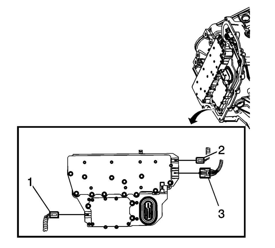
- Disconnect the output speed sensor electrical connector (2).
- Disconnect the shift position switch electrical connector (3).
- Disconnect the input speed sensor electrical connector (1).
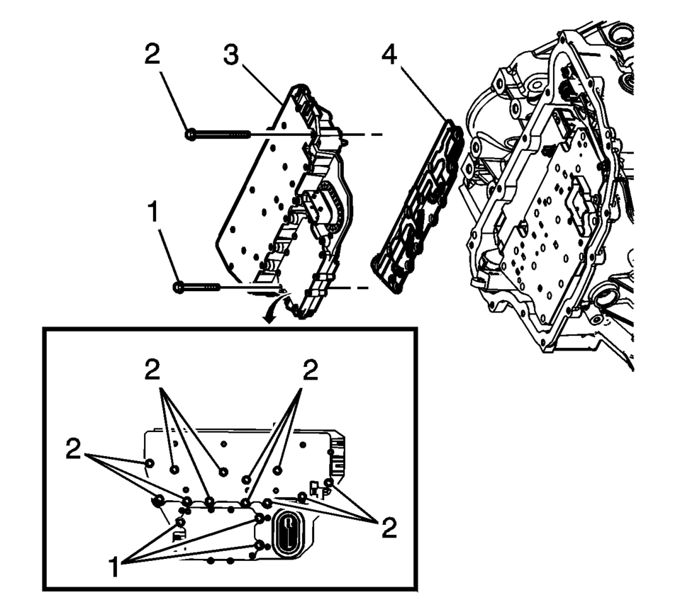
- Remove the 3 control solenoid valve assembly bolts (1) M5 x 40.5.
- Remove the 12 control solenoid valve assembly bolts (2) M6 x 97.
- Remove the control solenoid valve assembly with transmission control module (3).
- Remove the control solenoid valve assembly filter plate (4). Discard the filter plate. It is not reusable.
- Inspect the pressure switch seals for damage or contamination. Replace the control solenoid valve assembly as necessary.
- Inspect the channel plate bolt pass through holes for damage or burnelling. Any damage could cause leaking. Replace as necessary.
Caution:
Use care when removing or installing the filter plate assembly. A broken or missing retaining tab may not adequately secure the filter plate to the control solenoid valve assembly, resulting in possible damage or contamination.
- Installation Procedure
-
- Install a NEW control solenoid valve assembly filter plate (4) to prevent fluid leaks past the fluid seals.
- Install the control solenoid valve assembly with transmission control module (3).
- Hand start the control valve body bolts (1, 2).
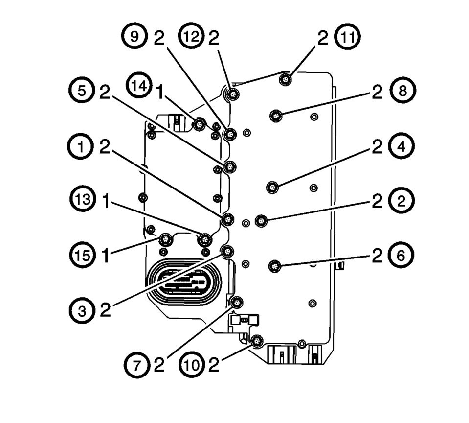
- Secure the 12 control solenoid valve assembly bolts (2) M6 x 97
and tighten in sequence to 12 Y (106 lb in)
.
- Secure the 3 control valve body bolts (1) M5 x 40.5
and tighten in sequence to 7 Y (62 lb in)
.
- Connect the input speed sensor electrical connector (1).
- Connect the output speed sensor electrical connector (2).
- Install the transmission control valve body cover. Refer to Control Valve Body Cover Replacement.
- After repairs, refer to Control Module References for programming and set up procedures.
- Perform the transmission adaptive values learn. Refer to Transmission Adaptive Values Learn.
Caution:
Use care when removing or installing the filter plate assembly. A broken or missing retaining tab may not adequately secure the filter plate to the control solenoid valve assembly, resulting in possible damage or contamination.
Caution:
Refer to Fastener Caution.
 Control Solenoid Valve and Transmission Control Module Assembly Installation
Control Solenoid Valve and Transmission Control Module Assembly Installation
Callout
Component Name
1
Control Solenoid V ...

Other materials:
Tires
Every new GM vehicle has high-quality tires made by a leading tire manufacturer.
See the warranty manual for information regarding the tire warranty and where to
get service. For additional information refer to the tire manufacturer.
Warning
. Poorly maintained and improperly used tires are ...
Recreational Vehicle Towing
Recreational vehicle towing means towing the vehicle behind another vehicle,
such as a motor home. The two most common types of recreational vehicle towing are
known as dinghy towing and dolly towing. Dinghy towing is towing the vehicle with
all four wheels on the ground. Dolly towing is towin ...
Drive Range, Third Gear (Gen 2)
As vehicle speed increases and operating conditions become appropriate, the transmission
control module (TCM) processes input signals from the automatic transmission input
and output speed sensors, the throttle position sensor and other vehicle sensors
to determine the precise moment to comman ...

0.0052