Chevrolet Sonic Repair Manual: Control Valve Channel Plate Cleaning and Inspection (6T30/40/45/50 - Gen 2)
|
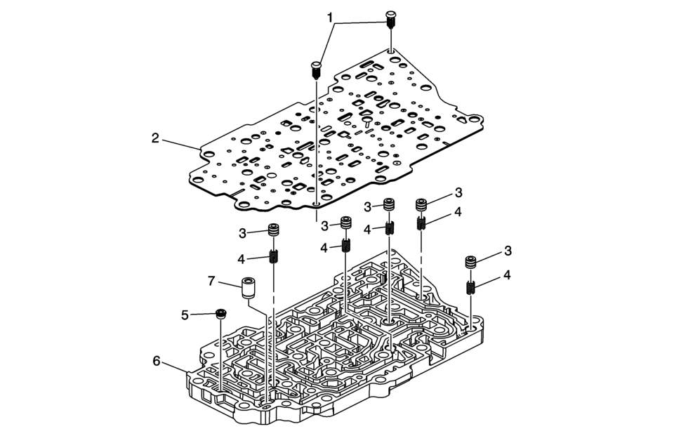
Callout |
Component Name |
|---|---|
|
1 |
Control Valve Body Spacer Plate Retainer |
|
2 |
Channel Plate to Valve Body Spacer Plate Assembly |
|
3 |
Actuator Feed Accumulator Piston (Qty: 5) |
|
4 |
Actuator Feed Accumulator Spring (Qty: 5) |
|
5 |
Variable Hi and 2-3-4 Clutch Housing Valve Ball |
|
6 |
Valve Channel Plate Note: Inspect the channel plate bolt pass through holes for damage or brinelling. Any damage will cause incorrect pressure switch operation. Replace as necessary. |
|
7 |
Control Valve Channel Plate Ball Spring Assembly |

 Definitions and Abbreviations
Throttle Positions
Engine Braking
A condition where the engine is used to slow the vehicle by manually
downshifting during a zero throttle coastdown.
Full Throttle Down ...
Other materials:
Engine Heater
The engine heater can provide easier starting and better fuel economy during
engine warm-up in cold weather conditions at or below −18°C (0°F). Vehicles with
an engine heater should be plugged in at least four hours before starting.
1. Turn off the engine.
2. Open the hood and unwrap ...
Steering Gear Boot Replacement
Special Tools
CH-804 Tensioner
For equivalent regional tools, refer to Special Tools.
Removal Procedure
Raise and support the vehicle. Refer to Lifting and Jacking the Vehicle.
Remove the steering linkage outer tie rod. Refer to Steering Linkage
Outer Tie Rod Rep ...
Engine Oil Cooler Housing Installation
Clean the engine oil cooler housing to thermostat housing sealing surfaces.
Install 2 NEW gaskets.
h.\.\,.\\..,v:..//
Install the engine oil cooler inlet pipe (3).
Install the engine oil cooler housing (1) and the 5 engine oil cooler bolts (2)
and t ...

0.005