Chevrolet Sonic Repair Manual: Drive Range, Fifth Gear Default (Gen 2)
If the transmission encounters an electrical component malfunction, the transmission will default to Fourth gear. All solenoids will default to their normal state. If the torque converter clutch is applied, it will release. The transmission will remain in Drive Range?Fourth Gear Default until the condition is corrected. Reverse (R) range can also still be selected. This default action enables the vehicle to be safely driven to a service center.
- 1-2-3-4 Clutch Applies or Remains Applied
-
1234 Pressure Control (PC) Solenoid
The 1234 PC solenoid defaults to its normally-high state (ON), allowing actuator feed limit fluid to enter the PCS 1234 clutch fluid circuit. PCS 1234 clutch fluid is routed through orifice #20 to the 1-2-3-4 clutch regulator valve, and through orifice #17 to the 1-2-3-4 clutch boost valve. If the transmission is operating in Fifth or Sixth gear when an electrical malfunction occurs, the 1-2-3-4 clutch will apply. If the transmission is operating in First, Second, Third or Fourth gear when the electrical malfunction occurs, the 1-2-3-4 clutch remains applied.
1-2-3-4 Clutch Boost Valve
PCS 1234 clutch fluid pressure acts on a differential area, moving the 1-2-3-4 clutch boost valve against 1-2-3-4 clutch boost valve spring force, to block 1234 clutch fluid from entering the 1234 clutch feedback circuit, and opening the 1234 clutch feedback circuit to exhaust backfill. This results in the 1-2-3-4 clutch regulator valve moving to the full feed position, sending full 1234 clutch feed pressure (full line pressure) to the 1-2-3-4 clutch.
1-2-3-4 Clutch Regulator Valve
PCS 1234 clutch fluid moves the 1-2-3-4 clutch regulator valve, against 1-2-3-4 clutch regulator valve spring force, to the applied position. This allows drive fluid pressure to pass through the valve into the 1234 clutch fluid circuit. The 1234 clutch fluid is then routed to the 1-2-3-4 clutch boost valve and through orifice #19 to the 1-2-3-4 clutch.
1-2-3-4 Clutch
1234 clutch fluid enters the transmission case assembly and moves the 1-2-3-4 clutch piston against spring force to apply the 1-2-3-4 clutch plates.
Accumulator
PCS 1234 clutch fluid is also routed to an accumulator valve. The accumulator valve is used to dampen any pressure irregularities occurring in the PCS 1234 clutch fluid circuit. This helps to control clutch apply fluid pressure and clutch apply feel.
- 4-5-6 Clutch Applies or Remains Applied
-
R1/456 Pressure Control (PC) Solenoid
The R1/456 PC solenoid defaults to its normally-high state (ON), allowing actuator feed limit fluid to enter the PCS R1/456 clutch fluid circuit. PCS R1/456 clutch fluid is routed through orifice #11 to the R1/4-5-6 clutch regulator valve, and through orifice #34 to the R1/4-5-6 clutch boost valve. If the transmission is operating in First, Second or Third gear when an electrical malfunction occurs, the 4-5-6 clutch will apply. If the transmission is operating in Fourth, Fifth or Sixth gear when the electrical malfunction occurs, the 4-5-6 clutch remains applied.
R1/4-5-6 Clutch Boost Valve
PCS R1/456 clutch fluid pressure acts on a differential area, moving the R1/4-5-6 clutch boost valve against R1/4-5-6 clutch boost valve spring force, to block R1/456 clutch feed fluid from entering the R1/456 clutch feedback circuit, and opening the R1/456 clutch feedback circuit to exhaust backfill. This results in the R1/4-5-6 clutch regulator valve moving to the full feed position, sending full R1/456 clutch feed pressure (full line pressure) to the 4-5-6 clutch.
R1/4-5-6 Clutch Regulator Valve
PCS R1/456 clutch fluid moves the R1/4-5-6 clutch regulator valve, against R1/4-5-6 clutch regulator valve spring force, to the applied position. This allows line fluid pressure to pass through the valve into the R1/456 clutch feed circuit. R1/456 clutch feed fluid is then routed to the clutch select valve, the R1/4-5-6 clutch boost valve, and through orifices #9 and #12 to the spring end of the R1/4-5-6 clutch regulator valve. When the R1/4-5-6 clutch regulator valve is in this position, latch fluid exhausts through the valve allowing 456 clutch fluid to shuttle the #1 ball check valve.
#1 Ball Check Valve
Orificed 456 clutch fluid pressure seats the #1 ball check valve against the exhausting latch fluid passage. 456 clutch fluid is then directed into the latch circuit to replace the exhausting latch pressure and is routed to the clutch select valve. Latch fluid combines with clutch select valve spring force and holds the valve in this position during all six forward gear ranges.
Clutch Select Valve
R1/456 clutch feed fluid passes through the clutch select valve and enters the 456 clutch circuit. 456 clutch fluid is routed to the 4-5-6 clutch assembly, and through orifice #2 to the #1 ball check valve.
4-5-6 Clutch
456 clutch fluid enters the 3-5-reverse and 4-5-6 clutch housing assembly, and moves the 4-5-6 clutch piston against spring force and exhaust backfill pressure to apply the 4-5-6 clutch plates.
Accumulator
PCS R1/456 clutch fluid is also routed to an accumulator valve. The accumulator valve is used to dampen any pressure irregularities occurring in the PCS R1/456 clutch fluid circuit. This helps to control clutch apply fluid pressure and clutch apply feel.
- 3-5-Reverse Clutch Releases
-
35R Pressure Control (PC) Solenoid
If the transmission is in Third or Fifth gear when an electrical condition commands a protection mode, the 35R PC solenoid defaults to its normally-low state (OFF), allowing PCS 35R clutch fluid pressure to exhaust and the 3-5-reverse clutch to release. See Drive Range?Fourth Gear for a complete description of 3-5-reverse clutch release.
- 2-6 Clutch Releases
-
26 Pressure Control (PC) Solenoid
If the transmission is in Second or Sixth gear when an electrical condition commands a protection mode, the 26 PC solenoid defaults to its normally-low state (OFF), allowing PCS 26 clutch fluid pressure to exhaust and the 2-6 clutch to release. See Drive Range?Third Gear for a complete description of 2-6 clutch release.
- Torque Converter Clutch (TCC) Releases
-
Torque Converter Clutch (TCC) Pressure Control (PC) Solenoid
If the TCC is applied when an electrical condition commands a protection mode, the TCC PC solenoid defaults to its normally-low state (OFF), allowing PCS TCC fluid to exhaust and the TCC to release. See Drive Range?Sixth Gear for a complete description of TCC release.
- Drive Range, Fourth Gear Default ?#8201;Gen 2/Hybrid
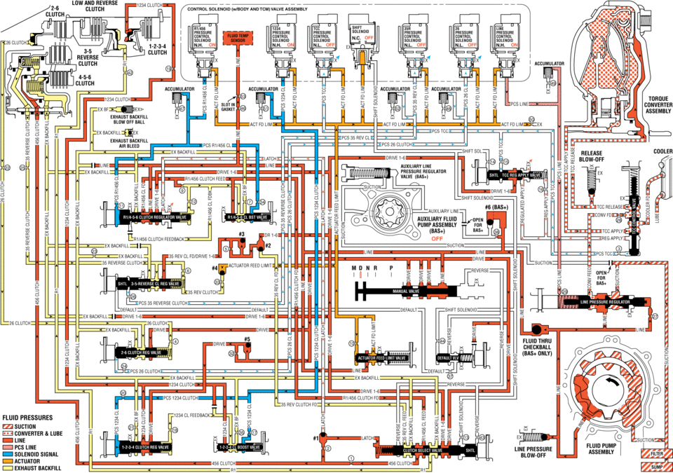
solenl1ld(wlbijdv valve assembly ni/i5 pres pre re press pressure n.h. un off off clutch accnmuumn clutch tdrdue cijnverter assemnlv exhaust == pcs ex backhll release cddler ahxiliarvline ex badkhll clutch feed el line auxiliary fluid clutch feedback off ex ii sucnuu lwe reverse clutch sun ree 35 rev clutch pcs reverse default sulenoid :ex drive pcszg clutch une exbackhll reverse v= clutchf =- fluid pressunes suction in eonverter lube line reg line pressure solenoid signal actuator :i exhaust
 Drive Range, Fifth Gear Default (Gen 1)
If the transmission encounters an electrical component malfunction, the transmission
will default to Fifth gear. All solenoids will default to their normal state. If
the torque converter clutch is ...
 Drive Range, First Gear (Gen 1)
As the vehicle speed increases, the transmission control module (TCM) receives
input signals from the automatic transmission input and output speed sensors, throttle
position sensor and other vehi ...
Other materials:
Steering Linkage Inner Tie Rod Replacement
Steering Linkage Inner Tie Rod Replacement
Callout
Component Name
Preliminary Procedures
Raise and support the vehicle. Refer to Lifting and Jacking the
Vehicle.
Remove the steering gear boot. Refer to Steering Gear Boot ...
Engine Oil Cooler Housing Removal
Remove the 2 engine oil cooler pipe bolts (1).
Remove the oil cooler pipe (2).
h.\.\,.\\..,v:..//
Remove the 5 engine oil cooler housing bolts (2).
Remove the engine oil cooler housing (1).
Remove the engine oil cooler inlet pi ...
Torque Converter Fluid Seal Replacement
Torque Converter Fluid Seal Replacement
Callout
Component Name
1
Torque Converter Fluid Seal Retainer
2
Torque Converter Fluid Seal
Special Tools
DT-47791-A Seal Installer
DT-6125- ...

0.0068