Chevrolet Sonic Repair Manual: Drive Range, Fifth Gear Default (Gen 1)
If the transmission encounters an electrical component malfunction, the transmission will default to Fifth gear. All solenoids will default to their normal state. If the torque converter clutch is applied, it will release. The transmission will remain in Drive Range?Fifth Gear Default until the condition is corrected. Reverse (R) range can also still be selected. This default action enables the vehicle to be safely driven to a service center.
- 3-5 Reverse Clutch Applies or Remains Applied
-
35R Pressure Control (PC) Solenoid 2
The 35R PC solenoid 2 defaults to its normally-high state (ON), allowing actuator feed limit fluid to enter the PCS 35 reverse clutch fluid circuit. PCS 35 reverse clutch fluid is routed through orifice #26 to the 3-5-reverse clutch regulator valve. If the transmission is operating in First, Second, Fourth or Sixth gear when an electrical malfunction occurs, the 3-5-reverse clutch will apply. If the transmission is operating in Third or Fifth gear when the electrical malfunction occurs, the 3-5-reverse clutch remains applied.
3-5-Reverse Clutch Regulator Valve
PCS 35 reverse clutch fluid, at the 3-5-reverse clutch regulator valve, opposes 3-5-reverse clutch regulator valve spring force and 35 reverse clutch feedback fluid pressure to regulate 35 reverse clutch feed/drive 1-6 pressure into the 35 reverse clutch circuit. The 35 reverse clutch fluid is then routed to the 3-5-reverse clutch assembly, through orifice #6 to the spring end of the 3-5-reverse clutch regulator valve and through orifice #33 to the #6 ball check valve. When the 3-5-reverse clutch regulator valve is in this position, PS3 fluid exhausts through the valve allowing the normally-closed #3 pressure switch to close.
3-5-Reverse Clutch
35 reverse clutch fluid enters the 3-5-reverse and 4-5-6 clutch housing assembly to move the 3-5 reverse clutch piston against spring force and compensator feed fluid pressure to apply the 3-5-reverse clutch plates.
#6 Ball Check Valve
35 reverse clutch feed fluid unseats the #6 ball check valve, allowing excess pressure to pass into the actuator feed limit circuit. This helps to control clutch apply fluid pressure and clutch apply feel.
- 4-5-6 Clutch Applies or Remains Applied
-
R1/456 Pressure Control (PC) Solenoid 3
The R1/456 PC solenoid 3 defaults to its normally-high state (ON), allowing actuator feed limit fluid to enter the PCS R1/456 clutch fluid circuit. PCS R1/456 clutch fluid is routed through orifice #11 to the R1/456 clutch regulator valve. If the transmission is operating in First, Second or Third gear when an electrical malfunction occurs, the 4-5-6 clutch will apply. If the transmission is operating in Fourth, Fifth or Sixth gear when the electrical malfunction occurs, the 4-5-6 clutch remains applied.
R1/4-5-6 Clutch Regulator Valve
PCS R1/456 clutch fluid, at the R1/4-5-6 clutch regulator valve, opposes R1/4-5-6 clutch regulator valve spring force and orificed R1/456 clutch feed fluid pressure to regulate line pressure into the R1/456 clutch feed circuit. R1/456 clutch feed fluid is then routed to the clutch select valve, through orifice #12 to the spring end of the R1/4-5-6 clutch regulator valve, and through orifice #34 to ball check valve #5. When the R1/4-5-6 clutch regulator valve is in this position, PS4 fluid exhausts through the valve allowing the normally-closed #4 pressure switch to close.
Clutch Select Valve
R1/456 clutch feed fluid passes through the clutch select valve and enters the 456 clutch circuit. 456 clutch fluid is routed to the 4-5-6 clutch assembly, and through orifice #2 to the #1 ball check valve.
#1 Ball Check Valve
Orificed 456 clutch fluid pressure seats the #1 ball check valve against the exhausting PS4 fluid passage. 456 clutch fluid is then directed into the CSV2 latch circuit to replace the exhausting PS4 pressure and is routed to the clutch select valve. CSV2 latch fluid combines with clutch select valve spring force and holds the valve in this position during all six forward gear ranges.
4-5-6 Clutch
456 clutch fluid enters the 3-5-reverse and 4-5-6 clutch housing assembly, and moves the 4-5-6 clutch piston against spring force and compensator feed pressure to apply the 4-5-6 clutch plates.
#5 Ball Check Valve
R1/456 clutch feed fluid unseats the #5 ball check valve, allowing excess pressure to pass into the actuator feed limit circuit. This helps to control clutch apply fluid pressure and clutch apply feel.
- 1-2-3-4 Clutch Releases
-
1234 Pressure Control (PC) Solenoid 5
If the transmission is in First, Second, Third or Fourth gear when an electrical condition commands a protection mode, the 1234 PC solenoid 5 defaults to its normally-low state (OFF), allowing PCS 1234 clutch fluid pressure to exhaust and the 1-2-3-4 clutch to release.
- 2-6 Clutch Releases
-
26 Pressure Control (PC) Solenoid 4
If the transmission is in Second or Sixth gear when an electrical condition commands a protection mode, the 26 PC solenoid 4 defaults to its normally-low state (OFF), allowing PCS 26 clutch fluid pressure to exhaust and the 2-6 clutch to release.
- Torque Converter Clutch (TCC) Releases
-
Torque Converter Clutch (TCC) Pressure Control (PC) Solenoid
If the TCC is applied when an electrical condition commands a protection mode, the TCC PC solenoid defaults to its normally-low state (OFF), allowing PCS TCC fluid to exhaust and the TCC to release.
- Drive Range?Fourth Gear Default (Some Models)
-
The transmission default gear may be Fourth, rather than Fifth gear, depending on engine size and effective final drive ratio. If the transmission encounters an electrical component malfunction, the transmission will default to Fourth gear. All solenoids will default to their normal state. If the torque converter clutch is applied, it will release. The transmission will remain in Drive Range? Fourth Gear Default until the condition has been corrected. Reverse (R) range can also still be selected. This default action enables the vehicle to be safely driven to a service center.
- Drive Range, Fifth Gear Default
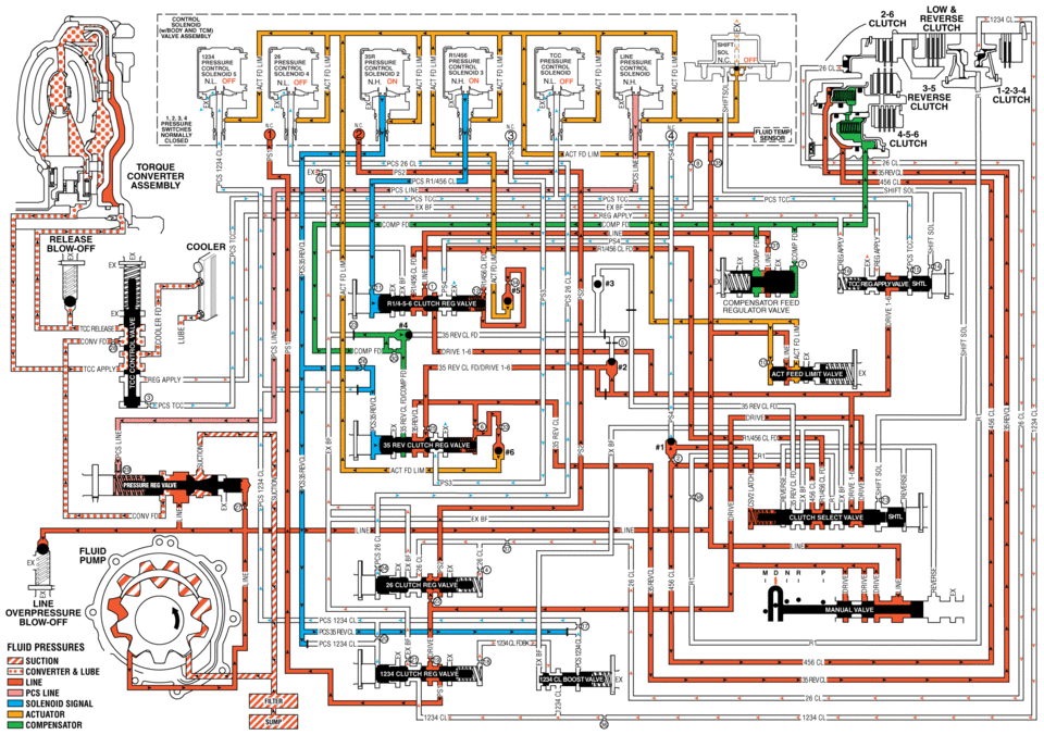
low reverse clutch 2e pressure pressure =- nl off n.h on nh on nl off nh. 3.5 reverse clutch clutch 4-5-6 tohoue converter pcslin release cooler ompensator feed unvfd drive 35 rev cl pcs cl blow-off fluid pressures suction converter lube line pcs line solenoid actuator compensator
 Drive Range, Fifth Gear (Gen 2)
As vehicle speed increases, the transmission control module (TCM) processes input
signals from the automatic transmission input and output speed sensors, the throttle
position sensor and other veh ...
 Drive Range, Fifth Gear Default (Gen 2)
If the transmission encounters an electrical component malfunction, the transmission
will default to Fourth gear. All solenoids will default to their normal state. If
the torque converter clutch i ...
Other materials:
Generator Replacement (LUV)
Removal Procedure
Disconnect the negative battery cable. Refer to Battery Negative Cable
Disconnection and Connection.
Raise and support the vehicle. Refer to Lifting and Jacking the Vehicle.
Remove the drive belt. Refer to Drive Belt Replacement.
Remove the drive bel ...
Ignition Transmission Lock Check
While parked, and with the parking brake set, try to turn the ignition to LOCK/OFF
in each shift lever position.
For automatic transmission vehicles, the ignition should turn to LOCK/OFF
only when the shift lever is in P (Park).
For manual transmission vehicles, the ignition should turn ...
Manual Transmission Shift Lever and Selector Lever Cable Replacement
Removal Procedure
Remove the battery tray. Refer to
Battery Tray Replacement.
\i
Disconnect the shift lever and selector cable ends (1)
from the transmission shift lever and selector levers.
Pull the cable retainers (2) to release the shift
leve ...

0.0085