Chevrolet Sonic Repair Manual: Drive Range, First Gear Engine Braking (Gen 2)
Note: Some models of the 6T30/40/45/50 automatic transmission are equipped with an electric auxiliary fluid pump for use in hybrid vehicles (BAS+). Hybrid vehicles do not require internal combustion engine (ICE) operation at all times. After a successful engine start, the hybrid powertrain control module (HPCM) may turn OFF the engine (Auto Stop) when not required for the current vehicle conditions. The engine will remain OFF while in Auto Stop mode, until such time that vehicle conditions require the engine to run. During Auto Stop mode the main fluid pump is no longer driven by the engine, and the auxiliary fluid pump is commanded ON to provide hydraulic fluid pressure to operate the transmission. This functional description of Drive Range?First Gear (Engine Braking), and its accompanying hydraulic circuit, is written for a non-hybrid transmission. For a hybrid (BAS+) transmission, the description and illustration are the same, with the exception that, when the engine is OFF, the main fluid pump is not operating and the auxiliary fluid pump is ON.
When the gear selector lever is moved to the Drive (D) range from the Neutral (N) position, the transmission will provide engine braking. In this operating range, the normally-high 1234 pressure control solenoid is commanded ON and, in the engine braking mode, the following changes occur within the hydraulic circuits.
- 1-2-3-4 Clutch Applies
-
Manual Valve
The manual valve is moved to the Drive (D) position and allows line fluid pressure to enter the drive fluid circuit. Drive fluid is then routed to the clutch select valve, the #5 ball check valve, and to the 2-6 clutch regulator valve.
#5 Ball Check Valve
Drive fluid unseats the #5 ball check valve and is routed to the 1-2-3-4 clutch regulator valve.
1234 Pressure Control (PC) Solenoid
The 1234 PC solenoid is commanded ON allowing actuator feed limit fluid to enter the PCS 1234 clutch fluid circuit. PCS 1234 clutch fluid is then routed through orifice #20 to the 1-2-3-4 clutch regulator valve, and through orifice #17 to the 1-2-3-4 clutch boost valve.
1-2-3-4 Clutch Regulator Valve
PCS 1234 clutch fluid, at the 1-2-3-4 clutch regulator valve, opposes 1-2-3-4 clutch regulator valve spring force and 1234 clutch feedback fluid pressure to regulate drive fluid pressure into the 1234 clutch fluid circuit. The 1234 clutch fluid is then routed to the 1-2-3-4 clutch boost valve and through orifice #19 to the 1-2-3-4 clutch.
1-2-3-4 Clutch Boost Valve
PCS 1234 clutch fluid pressure acts on a differential area, moving the 1-2-3-4 clutch boost valve against 1-2-3-4 clutch boost valve spring force, to regulate 1234 clutch fluid into the 1234 clutch feedback circuit. As PCS 1234 clutch fluid pressure is increased to a given value, the 1-2-3-4 clutch boost valve opens the 1234 clutch feedback circuit to exhaust backfill. This results in the 1-2-3-4 clutch regulator valve moving to the full feed position, sending full 1234 clutch feed pressure (full line pressure) to the 1-2-3-4 clutch.
1-2-3-4 Clutch
The 1234 clutch fluid enters the transmission case assembly and moves the 1-2-3-4 clutch piston against spring force to apply the 1-2-3-4 clutch plates.
Accumulator
PCS 1234 clutch fluid is also routed to an accumulator valve. The accumulator valve is used to dampen any pressure irregularities occurring in the PCS 1234 clutch fluid circuit. This helps to control clutch apply fluid pressure and clutch apply feel.
- Low and Reverse Clutch Remains Applied to Provide Engine Braking
-
Clutch Select Valve
Shift solenoid fluid, present at the valve from Park position, continues to hold the clutch select valve against clutch select valve spring force. R1/456 clutch feed fluid, also present at the valve from Park position, continues to pass into the R1 circuit to feed the low and reverse clutch. Drive fluid is present at the valve in preparation for a change of gears.
Low and Reverse Clutch
The low and reverse clutch remains applied until just before the 1-2 shift in order to provide engine braking.
- Drive Range, First Gear Engine Braking ?#8201;Gen 2/Hybrid
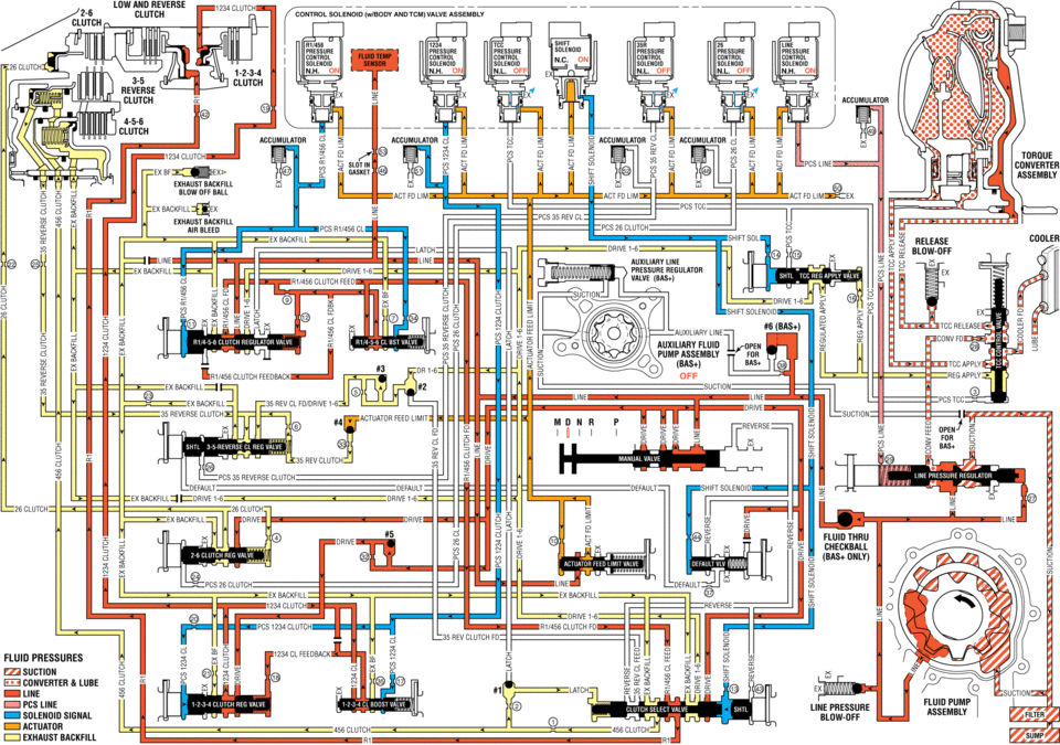
solenijid valve assembly n.h. un off off accnmumnn aceumhlatur exhaust actfdum ex n: exnaust backfill pcs clutch ex backhll release cddleh lwei ex backhll clutch feed el line (sh auxiliary fluid i: clutch feedback off ex ii suctiuu lwe ex 35 reverse clutch sun ree ..... 35 rev clutch pcs reverse clutch default clutch: fluid nmu eheckball pcszg clutch exbackhll reverse clutch ngv clutch fluid pressures in sucnou converter lube clutch line pressure solenoid signal clutch clutch :i exhaust backfill
 Drive Range, First Gear Engine Braking (Gen 1)
When the gear selector lever is moved to the Drive (D) range from the Neutral
(N) position, the transmission will provide engine braking. In this operating range,
the normally-low 1234 pressure co ...
 Drive Range, Second Gear (Gen 1)
As vehicle speed increases and operating conditions become appropriate, the transmission
control module (TCM) processes input signals from the automatic transmission input
and output speed sensors ...
Other materials:
Instrument Panel Airbag Arming Status Display Replacement
Instrument Panel Airbag Arming Status Display Replacement
Callout
Component Name
Preliminary Procedure
Remove the heater and air conditioning control. Refer to Heater and Air
Conditioning Control Replacement.
...
Brake Pipe and Hose Inspection
Warning: Refer to Brake Fluid Irritant Warning.
Caution: Refer to Brake Fluid Effects on Paint and Electrical Components
Caution.
Visually inspect all of the brake pipes for the following conditions:
Kinks, incorrect routing, missing or damaged retainers
Leaking fittin ...
Engine Oil Cooler Inlet Pipe Replacement (LUW)
Removal Procedure
Drain the cooling system. Refer to Cooling System Draining and Filling.
Remove the exhaust manifold with catalytic converter. Refer to Exhaust
Manifold with Catalytic Converter Replacement.
Remove the engine oil cooler pipe bolts (1) an ...

0.0053