Chevrolet Sonic Repair Manual: Drive Range, Second Gear (Gen 1)
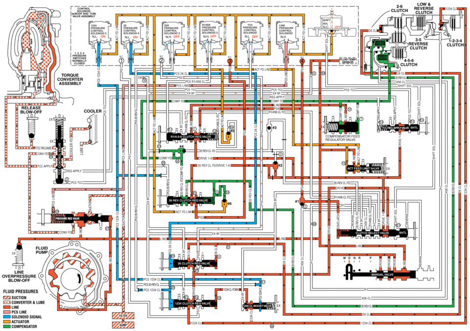
As vehicle speed increases and operating conditions become appropriate, the transmission control module (TCM) processes input signals from the automatic transmission input and output speed sensors, the throttle position sensor and other vehicle sensors to determine the precise moment to command ON the normally-low 2-6 pressure control solenoid 4 and shift the transmission into Second gear. The manual valve remains in the Drive (D) position and line pressure continues to feed the drive fluid circuit.
- 2-6 Clutch Applies
-
26 Pressure Control (PC) Solenoid 4
The 26 PC solenoid 4 is commanded ON, allowing actuator feed limit fluid to enter the PCS 26 clutch fluid circuit. PCS 26 clutch fluid is then routed through orifice #24 to the 2-6 clutch regulator valve.
2-6 Clutch Regulator Valve
PCS 26 clutch fluid, at the 2-6 clutch regulator valve, opposes 2-6 clutch regulator valve spring force and orificed 26 clutch fluid pressure to regulate drive fluid pressure into the 26 clutch circuit. 26 clutch fluid is then routed through orifice #37 to the 2-6 clutch assembly in the transmission case, and through orifice #4 to the spring end of the 2-6 clutch regulator valve. With the 2-6 clutch regulator valve in this position, PS2 fluid is allowed to exhaust and the normally-closed PS2 switch closes.
2-6 Clutch
The 26 clutch fluid from the 2-6 clutch regulator valve is routed through the transmission case to the 2-6 clutch piston assembly. The 26 clutch fluid pressure moves the piston against 2-6 clutch spring force to apply the 2-6 clutch plates.
- Drive Range, Second Gear
low reverse cl clutch pressure pressure convrol nl on n.h nh on: nl clutch act fd um torque cl converter assemblv pcs ex bf -comp release pcs tdc cooler compensator feed regulator valve sol blow-off fluid pressures suction converter lube line pcs line solenoid actuator compensatdr
 Drive Range, First Gear Engine Braking (Gen 2)
Note: Some models of the 6T30/40/45/50 automatic transmission are equipped with
an electric auxiliary fluid pump for use in hybrid vehicles (BAS+). Hybrid vehicles
do not require internal combusti ...
 Drive Range, Second Gear (Gen 2)
As vehicle speed increases and operating conditions become appropriate, the transmission
control module (TCM) processes input signals from the automatic transmission input
and output speed sensors ...
Other materials:
Rear Side Door Lock Cylinder Opening Cover Replacement
Rear Side Door Lock Cylinder Opening Cover Replacement
Callout
Component Name
1
Rear Side Door Lock Cylinder Opening Cover
Procedure
Remove the rear side door lock cylinder, Do Not
remove the outside door han ...
Sunroof Window Height and Opening Fit Adjustment
Note: Correct adjustment cannot be achieved if the sunroof window
is closed from vent position.
Cycle the sunroof window from full open to closed position.
.,
Note: Do Not remove or lower headliner to access sunroof window
screws.
Loosen the adjusting screws on ...
Replacing Airbag System Parts after a Crash
Warning: A crash can damage the airbag systems in the vehicle. A damaged
airbag system may not work properly and may not protect you and your passenger(s)
in a crash, resulting in serious injury or even death. To help make sure the
airbag systems are working properly after a crash, have ...

0.0059