Chevrolet Sonic Repair Manual: Drive Range, Third Gear (Gen 2)
As vehicle speed increases and operating conditions become appropriate, the transmission control module (TCM) processes input signals from the automatic transmission input and output speed sensors, the throttle position sensor and other vehicle sensors to determine the precise moment to command OFF the normally-low 26 pressure control solenoid. At the same time the 35R pressure control solenoid is also commanded ON to regulate 3-5 clutch apply, and the transmission shifts into Third gear. The manual valve remains in the Drive (D) position and line pressure continues to feed the drive fluid circuit.
- 3-5-Reverse Clutch Applies
-
35R Pressure Control (PC) Solenoid
The 35R PC solenoid is commanded ON, allowing actuator feed limit fluid to enter the PCS 35 reverse clutch fluid circuit. PCS 35 reverse clutch fluid is routed through orifice #26 to the 3-5-reverse clutch regulator valve.
3-5-Reverse Clutch Regulator Valve
PCS 35 reverse clutch fluid, at the 3-5-reverse clutch regulator valve, opposes 3-5-reverse clutch regulator valve spring force and 35 reverse clutch feedback fluid pressure to regulate 35 reverse clutch feed/drive 1-6 pressure into the 35 reverse clutch circuit. The 35 reverse clutch fluid is then routed through orifice #25 to the 3-5-reverse clutch assembly, through orifice #6 to the spring end of the 3-5-reverse clutch regulator valve and through orifice #33 to the #4 ball check valve.
3-5-Reverse Clutch
35 reverse clutch fluid enters the 3-5-reverse and 4-5-6 clutch housing assembly to move the 3-5-reverse clutch piston against spring force and exhaust backfill fluid pressure to apply the 3-5-reverse clutch plates.
#4 Ball Check Valve
35 reverse clutch feed fluid unseats the #4 ball check valve, allowing excess pressure to pass into the actuator feed limit circuit. This helps to control clutch apply fluid pressure and clutch apply feel.
Accumulator
PCS 35 reverse clutch fluid is also routed to an accumulator valve. The accumulator valve is used to dampen any pressure irregularities occurring in the PCS 35 reverse clutch fluid circuit. This helps to control clutch apply fluid pressure and clutch apply feel.
- 2-6 Clutch Releases
-
26 Pressure Control (PC) Solenoid
The 26 PC solenoid is commanded OFF, allowing PCS 26 clutch fluid to exhaust from the 2-6 clutch regulator valve.
2-6 Clutch Regulator Valve
2-6 clutch regulator valve spring force moves the valve to the released position, allowing 26 clutch fluid from the 2-6 clutch to pass through the valve and enter the exhaust backfill fluid circuit.
2-6 Clutch
2-6 clutch spring force moves the 2-6 clutch piston to release the 2-6 clutch plates and force 26 clutch fluid to exhaust from the transmission case assembly. The exhausting 26 clutch fluid pressure is routed to the 2-6 clutch regulator valve where it enters the exhaust backfill fluid circuit.
- Drive Range, Third Gear ?#8201;Gen 2/Hybrid
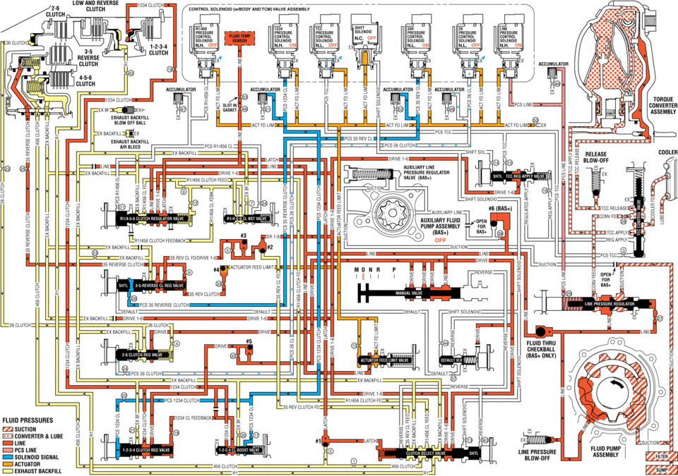
solenl1ld(wlbijdv valve assembly n.h. off off clutch accnmuumn ancnmuumn clutch tdrdue converter assemnlv exhaust act fd fd ex exnaust backfill iepcs ex backhll release cddleh blow-off linei ex badkhll_ pressure valve in :. line release cow fd clutch feedback off ex ii sucnuu lwe as reverse clutch feed mu pcs reverse sulenoid :ex -drive drive iv fluid mu ehedkball um pcs 2e clutch _default ex reverse fluid pnessunes sucnou converter lube lime line pressure solenoid signal 1_ clutch clutch :i exhaust backfill
 Drive Range, Third Gear (Gen 1)
As vehicle speed increases and operating conditions become appropriate, the transmission
control module (TCM) processes input signals from the automatic transmission input
and output speed sensors ...
 Drive Sprocket, Driven Sprocket, and Drive Link Cleaning and Inspection
Drive Sprocket, Driven Sprocket, and Drive Link Cleaning and Inspection
Callout
Component Name
1
Drive Sprocket Thrust W ...
Other materials:
Tire and Loading Information Label
A vehicle-specific Tire and Loading Information label is attached to the vehicle's
center pillar (B-pillar). The Tire and Loading Information label shows the number
of occupant seating positions (1), and the maximum vehicle capacity weight (2) in
kilograms and pounds.
The Tire and Loadi ...
Rear Seat Shoulder Belt Guide Opening Bezel Replacement
Rear Seat Shoulder Belt Guide Opening Bezel Replacement
Callout
Component Name
1
Rear Seat Shoulder Belt Opening Bezel
Procedure
Push inward and upward from the front of the bezel to release from the
seat back ...
Air Cleaner Assembly Replacement
Air Cleaner Assembly Replacement
Callout
Component Name
1
Air Cleaner Outlet Duct Clamp.
Procedure
Loosen clamp and remove air cleaner outlet duct from air cleaner assembly.
2
Mass ...

0.0061