Chevrolet Sonic Repair Manual: Front Wheel Drive Shaft Outer Joint and Boot Replacement
Special Tools
DT-35910 Drive Axle Boot Clamp Pliers
For equivalent regional tools, refer to Special Tools
- Disassemble Procedure
-
- Remove the wheel drive shaft from the vehicle. Refer to Front Wheel Drive Shaft Replacement.
- Install the drive axle shaft (1) in a soft jawed vice.
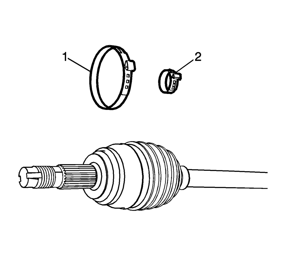
- Using a pair of side cutters, remove the outer boot clamp (1) and the inner boot clamp (2).
- Discard the boot clamps (1) and (2). Use NEW clamps only.
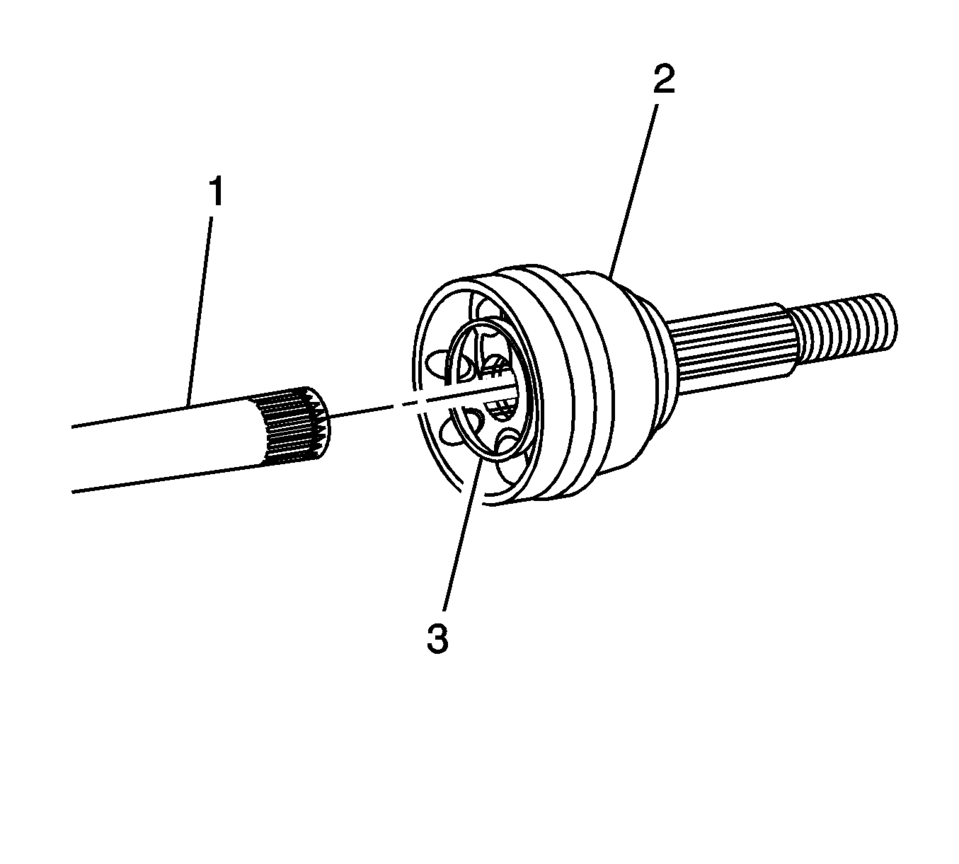
- Remove the CV joint (2) from the wheel drive shaft (1) while tapping the inner race (3) using a bronze bar and a hammer.
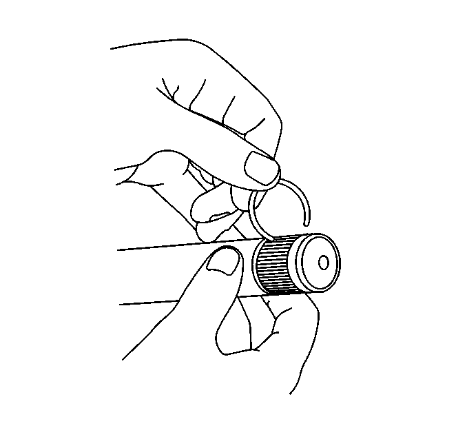
- Using the appropriate tool, remove and discard the retaining clip.
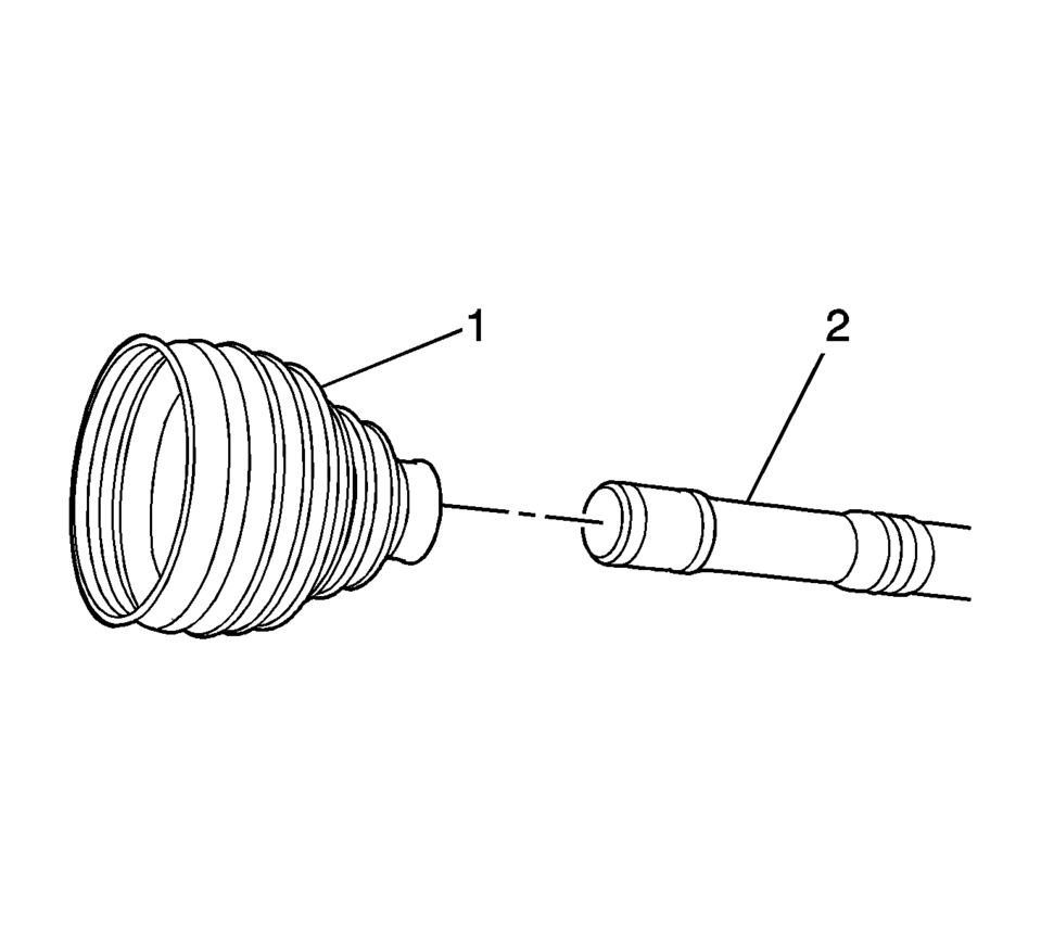
- Remove the boot (1) from the wheel drive shaft (2).
- Inspect the outer CV joint for damage and wear. Refer to Wheel Drive Shaft Outer Joint Inspection.
Caution:
Do not cut through the wheel drive shaft inboard or outboard boot during service. Cutting through the boot may damage the sealing surface of the housing and the tripot or the constant velocity joint bushing. Damage to the sealing surface may lead to water and dirt intrusion and premature wear of the constant velocity joint.
- Assemble Procedure
-
- Position the boot (1) on the wheel drive shaft (2).
- Using the appropriate tool, install the NEW retaining clip.
- Ensure that the boot (1) is properly seated in the grooved (2) wheel drive shaft (3).
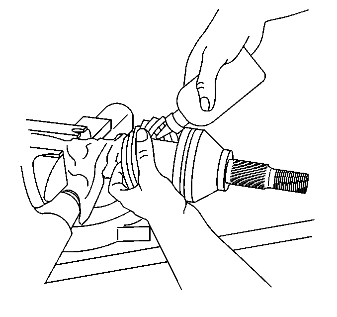
- Place approximately half the lubricant from the service kit inside the outboard boot and pack the CV joint with the remaining lubricant.
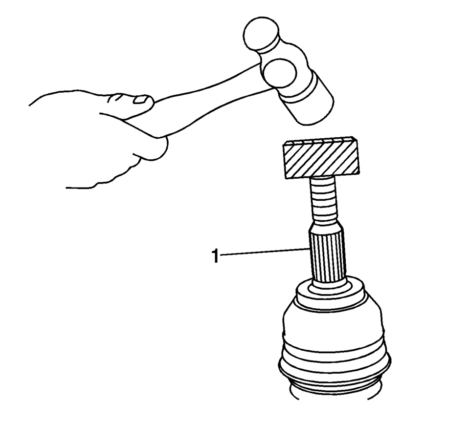
- Using a block of wood and a hammer, install the CV joint (1) on the wheel drive shaft.
- Install the inner boot clamp (2) and the outer boot clamp (1).
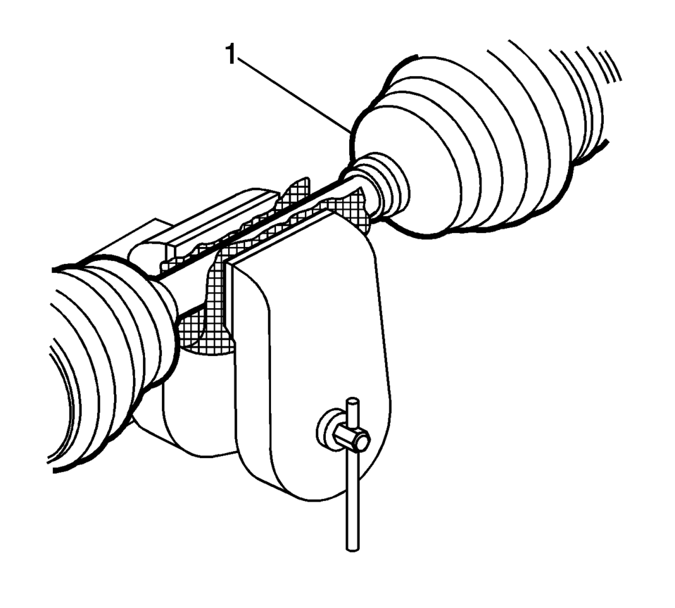
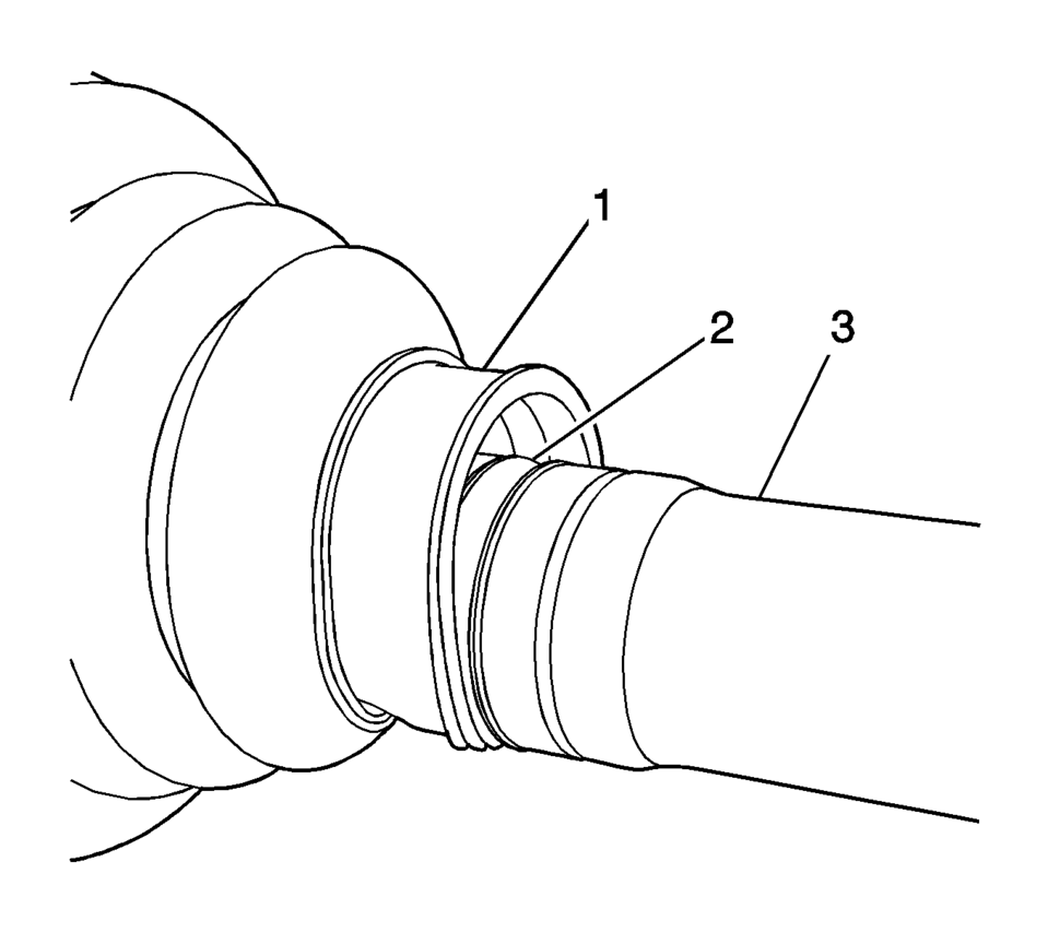
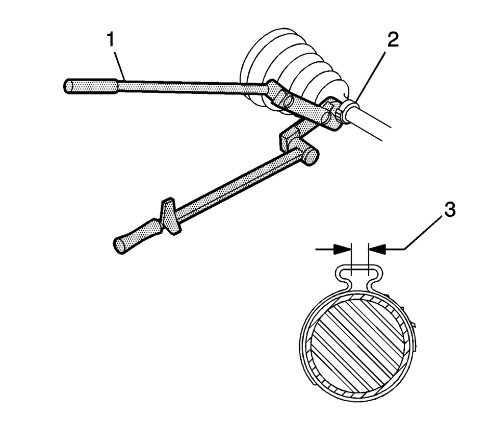
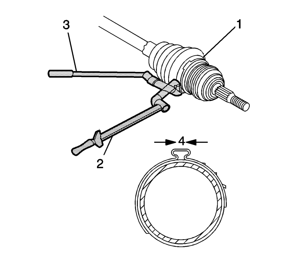
- Using the DT-35910 pliers and a torque or ratchet wrench and
breaker bar (1), close the boot clamp (2) until the gap (3) measures
1.9 mm (0.07 in)
.
- Using the DT-35910 pliers and a torque or ratchet wrench (2) and
breaker bar (3), close the boot clamp (1) until the gap (4) measures
1.7 mm (0.06 in)
.
- Distribute the lubricant within the outer CV joint by moving it in a circular motion at least four to five times.
- Remove the wheel drive shaft from the bench vise.
- Install the wheel drive shaft assembly. Refer to Front Wheel Drive Shaft Replacement.
Note:
Ensure that the boot clamp is properly positioned around the entire circumference of the boot.
 Front Wheel Drive Shaft Inner Joint and Boot Replacement
Special Tools
DT-35910 Drive Axle Boot Clamp Pliers
For equivalent regional tools, refer to Special Tools.
Disassemble Procedure
Note: There are types of inner joints available. If ...
 Front Wheel Drive Shaft Replacement
Special Tools
J-45859 Axle Remover
For regional equivalent tools, refer to Special Tools.
Removal Procedure
Raise and support the vehicle. Refer to Lifting and Jacking the Vehicle.
...
Other materials:
Compact Spare Tire
Warning
Driving with more than one compact spare tire at a time could result in loss
of braking and handling. This could lead to a crash and you or others could be injured.
Use only one compact spare tire at a time.
If this vehicle has a compact spare tire, it was fully inflated when new; howe ...
Liftgate Replacement
Liftgate Replacement
Callout
Component Name
Preliminary Procedures
Disconnect the electrical connectors.
Disconnect the liftgate struts. Refer to Liftgate Strut Replacement.
Remove the body lock pillar upper trim. Refe ...
Instrument Panel Fuse Block Access Hole Cover Replacement (Without AAL)
Instrument Panel Fuse Block Access Hole Cover Replacement
Callout
Component Name
1
Instrument Panel Fuse Block Access Hole Cover
Procedure
Grasp the lower edge of the fuse block cover and pull outward disengaging ...

0.0069