Chevrolet Sonic Repair Manual: Front Wheel Drive Shaft Replacement
Special Tools
J-45859 Axle Remover
For regional equivalent tools, refer to Special Tools.
- Removal Procedure
-
- Raise and support the vehicle. Refer to Lifting and Jacking the Vehicle.
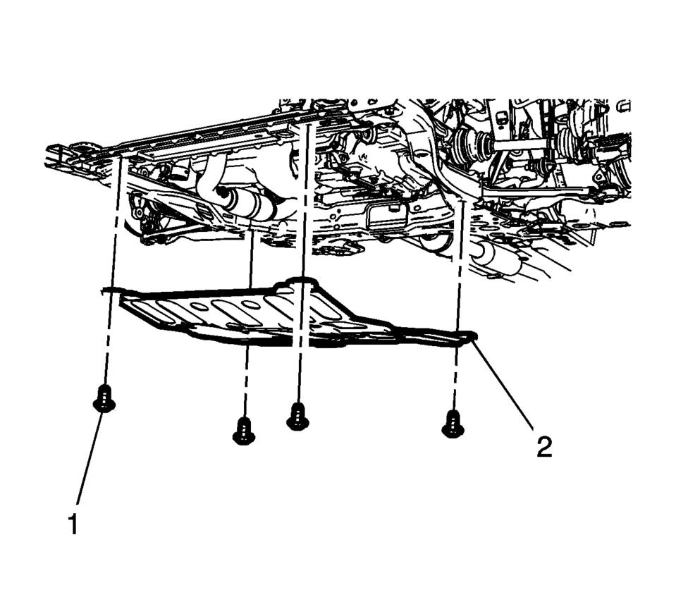
- Remove the front suspension skid plate bolts (1) and the front suspension skid plate (2).
- Remove the tire and wheel assembly. Refer to Tire and Wheel Removal and Installation.
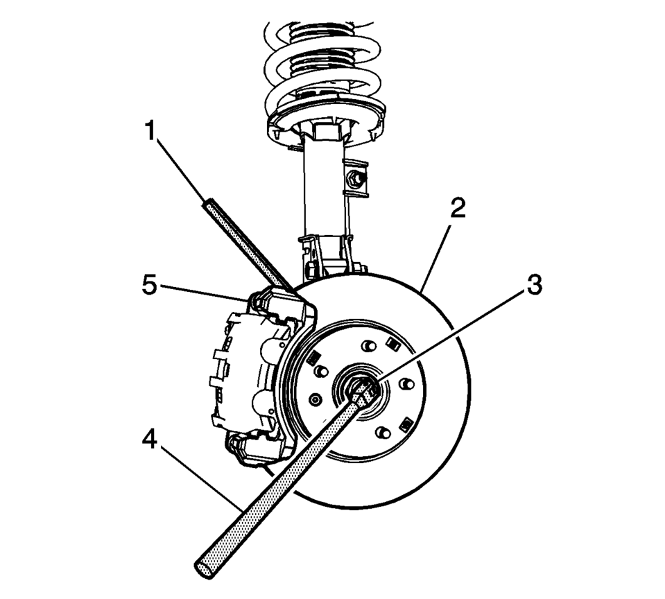
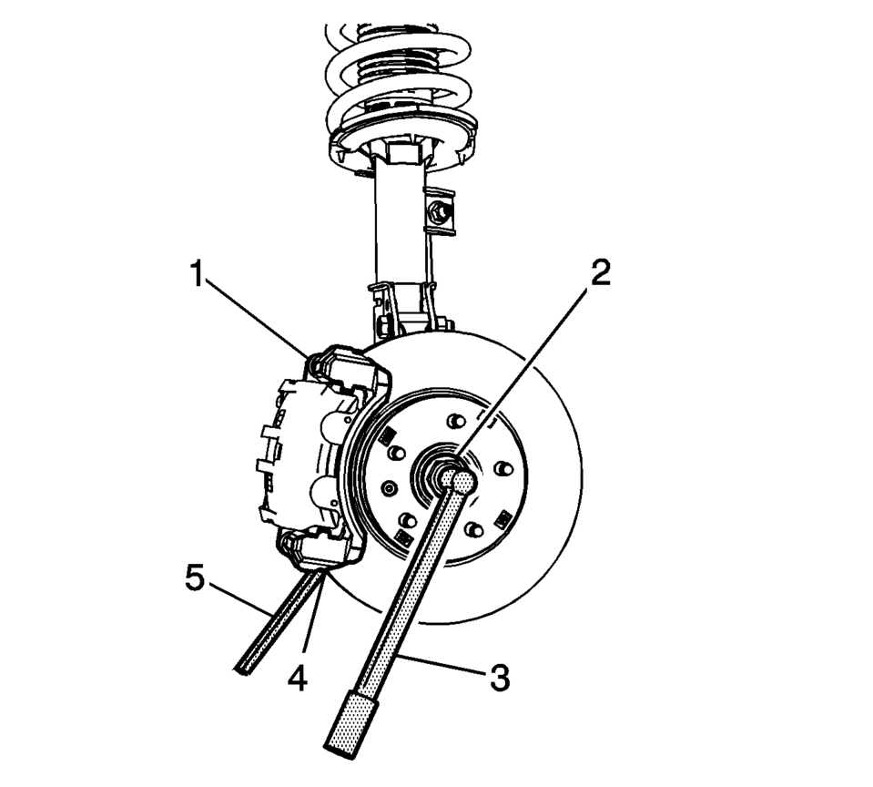
- Insert a brass drift or punch (1) in the cooling fins of the front brake rotor (2).
- Rotate the brake rotor until it comes in contact with the brake caliper mount bracket (5).
- Using the proper size socket (3) and a breaker bar (4), loosen the wheel drive shaft nut.
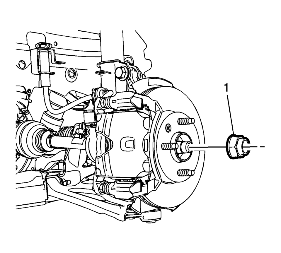
- Remove and discard the wheel drive shaft nut (1). Replace with NEW only.
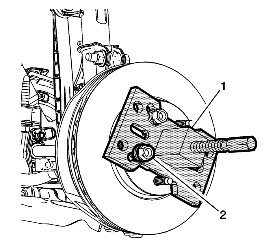
- Attach the J-45859 remover (1) to the wheel hub using the wheel lug nuts (2).
- Using the J-45859 remover (1) , separate the wheel drive shaft from the wheel bearing/hub.
- Remove the stabilizer shaft link from the front strut. Refer to Stabilizer Shaft Link Replacement.
- Remove the outer tie rod end from the steering knuckle. Refer to Steering Linkage Outer Tie Rod Replacement.
- Remove the lower control arm bolt from the steering knuckle. Refer to Lower Control Arm Replacement.
- With the aide of an assistant, move the steering knuckle to the side.
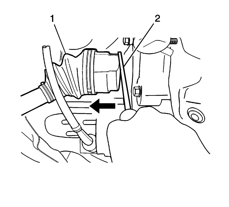
- Using a long screw driver (2), remove the wheel drive shaft (1) from the transmission.
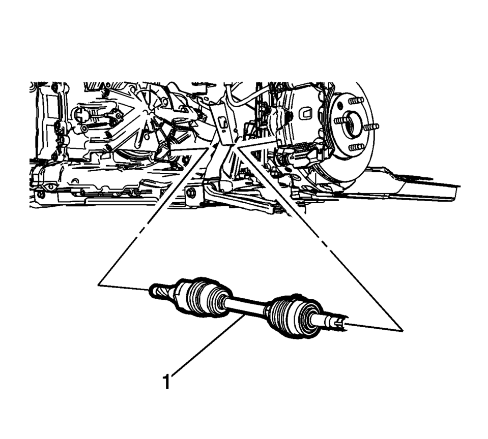
- Remove the wheel drive shaft (1) from the vehicle.
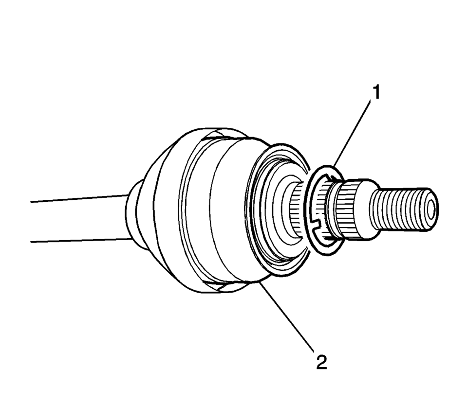
- Remove and discard the washer (1) from the wheel drive shaft (2). Do not re-use the washer, replace with NEW only.
Caution:
Make sure that the wheel drive shaft nut is fully un-staked to avoid damage to the wheel drive shaft threads during the removal of the wheel drive shaft nut. Failure to follow these instructions could result in wheel, nut, and/or stud damage.
Note:
Reverse the wheel lug nuts and washers so the flat part of the wheel nut is facing the washers.
Note:
If there is no washer on the wheel drive shaft, install a NEW washer.
- Installation Procedure
-
- Position the wheel drive shaft (1) in the vehicle.
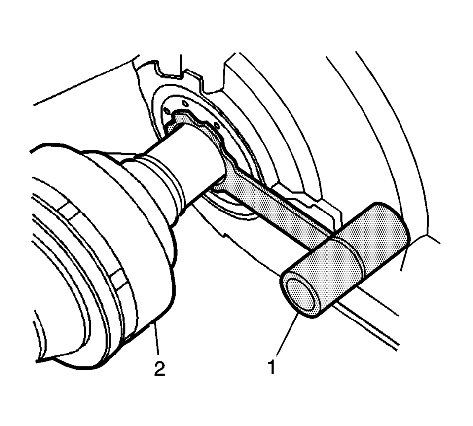
- Install the special tool (1) in the output shaft seal.
- Install the wheel drive shaft (2).
- Remove the special tool (1).
- Install the lower control arm ball joint bolt to the steering knuckle. Refer to Lower Control Arm Replacement.
- Install the stabilizer shaft link to the front strut. Refer to Stabilizer Shaft Link Replacement.
- Install the outer tie rod to the steering knuckle. Refer to Steering Linkage Outer Tie Rod Replacement.
- Install the NEW wheel drive shaft nut (1).
- Insert a brass drift or punch (5) in the cooling fins of the front brake rotor (4).
- Rotate the brake rotor until it comes in contact with the brake caliper mount bracket (1).
- There are two types of the wheel drive shaft nuts, which have different tightening torque specifications. Check the style nut that is on the vehicle when staking the nut.
- Style 1 nut has the thin collar (1.5 mm) thickness.
- Style 2 nut has the thick collar (2.7 mm) thickness.
- Using the proper size socket and torque wrench, tighten the NEW wheel drive shaft nut to:
Caution:
Refer to Fastener Caution.
Note:
- For Style 1, 330 Y (244 lb ft)
- For Style 2, First Pass: 50 Y (37 lb ft)
- For Style 2, Final Pass: plus 60 degrees.
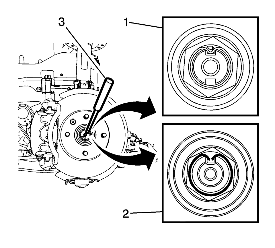
- Using appropriate tools (3), stake the wheel drive shaft nut collar into the slot on the wheel drive shaft.
- Style 1: Stake the center of the wheel drive shaft nut (1) and ensure
it is fully staked. DO NOT fractured the wheel drive shaft nut. Each side
of the stake should be in contact with the slot in the wheel drive shaft.
The gap between the bottom of the stake in the wheel drive shaft nut and
the bottom of the slot in the wheel drive shaft should be less than 1 mm
(0.039 in)
.
- Style 2: Evenly split the center of the wheel drive shaft nut (2) and ensure that it is fully staked. Each side of the stake should be in contact and approximately 45° to each side of the slot in the wheel drive shaft.
- Install the front suspension skid plate (2).
- Install the front suspension skid plate bolts (1) and tighten to 22 Y (16 lb ft).
- Install the tire and wheel assembly. Refer to Tire and Wheel Removal and Installation.
- Remove the support and lower the vehicle.
 Front Wheel Drive Shaft Outer Joint and Boot Replacement
Special Tools
DT-35910 Drive Axle Boot Clamp Pliers
For equivalent regional tools, refer to Special Tools
Disassemble Procedure
Remove the wheel drive shaft from the vehicle. Refer ...
 Front Wheel Drive Shaft Seal Replacement - Case Side
Front Wheel Drive Shaft Seal Replacement - Case Side
Callout
Component Name
1
Front Wheel Drive Shaft Oil Seal
Specia ...
Other materials:
Heater and Air Conditioning Evaporator and Blower Module Removal and Installation
Heater and Air Conditioning Evaporator and Blower Module Removal and
Installation
Callout
Component Name
Preliminary Procedures
Recover the refrigerant. Refer to Refrigerant Recovery and Recharging.
Drain the cooling sy ...
Drive Range, Third Gear (Gen 1)
As vehicle speed increases and operating conditions become appropriate, the transmission
control module (TCM) processes input signals from the automatic transmission input
and output speed sensors, the throttle position sensor and other vehicle sensors
to determine the precise moment to comman ...
System temporarily unavailable
While operating the Nissan Armada, certain road environments such as winding
mountain routes, steep inclines, sharp curves, narrow lanes, or areas under construction
can temporarily affect the performance of the driver assistance systems. In these
situations, the sensors may incorrectly id ...

0.0054