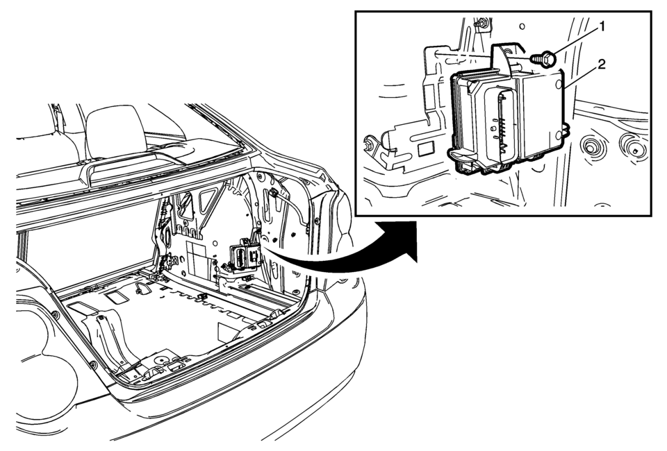
Chevrolet Sonic Repair Manual: Fuel Pump Flow Control Module Replacement
|
Callout |
Component Name |
|---|---|
Preliminary Procedures
|
|
|
1 |
Fuel Pump Control Module Fastener Caution: Refer to Fastener Caution.
10 Y (89 lb in) |
|
2 |
Fuel Pump Control Module Caution:
|
 Fuel Injector Replacement
Fuel Injector Replacement
Callout
Component Name
Preliminary Procedure
Disconnect battery negative cable. Refer to Battery Negative ...
 Fuel Tank Fuel Pump Module Replacement
Special Tools
EN-48279 Fuel Sender Lock Ring Tool
For equivalent regional tools, refer Special Tools.
Removal Procedure
Relieve the fuel system pressure. Refer to Fuel Press ...
Other materials:
Instrument Panel Compartment Replacement
Instrument Panel Compartment Replacement
Callout
Component Name
Preliminary Procedure
Remove the right instrument panel upper trim panel. Refer to Instrument
Panel Upper Trim Panel Replacement - Right Side.
...
Seat Belt Service Precautions
Note: If the vehicle has been in a collision, refer to Repairs
and Inspections Required After a Collision for additional information.
Do not bleach or dye the seat belt webbing. Use only the following items
in order to clean the seat belt webbing:
A mild soap and water ...
Electronic Ignition System Description
Electronic Ignition System Operation
The electronic ignition system produces and controls the high energy secondary
spark. This spark ignites the compressed air/fuel mixture at precisely the correct
time, providing optimal performance, fuel economy, and control of exhaust emissions.
...

0.0056