Chevrolet Sonic Repair Manual: Lift Plate and Holding Fixture Installation
|
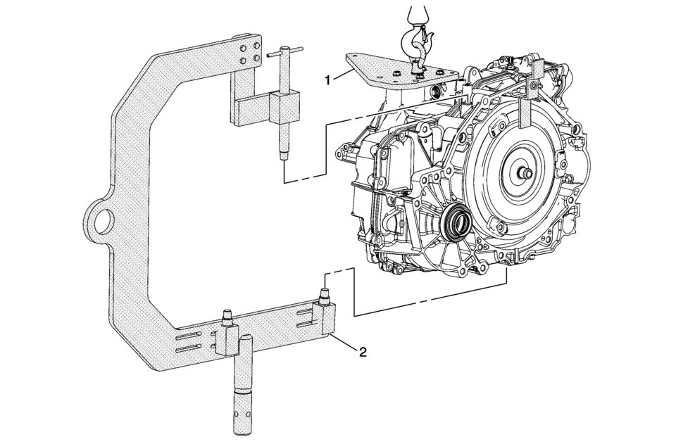
Callout |
Component Name |
|---|---|
|
1 |
DT-47811-A Transmission Lift Plate Warning: Handle with care, the transmission assembly weighs over 83 Kg (183 lbs). Bodily injury could occur if not handled properly. Caution: Refer to Fastener Caution. Procedure
Tighten bolts and nut. Tighten
12 Y (106 lb in) Special Tools
DT-47811-A Transmission Lift Plate For equivalent regional tools, refer to Special Tools. |
|
2 |
DT-46625 Transmission Holding Fixture Procedure
13 Y (10 lb ft) Special Tools
DT-46625-10 Holding Fixture Adapter For equivalent regional tools, refer to Special Tools. |
 Internal Components Removal
Internal Components Removal
Callout
Component Name
1
1??? Clutch Backing Plate Retainer Ring
Warning: The retain ...
 Lift Plate and Holding Fixture Removal
Lift Plate and Holding Fixture Removal
Callout
Component Name
1
DT-46625 Transmission Holding Fixture
For equivalent ...
Other materials:
Rear Side Door Window Regulator Motor Replacement
Rear Side Door Window Regulator Motor Replacement
Callout
Component Name
Warning: Refer to Glass and Sheet Metal Handling Warning.
Preliminary Procedure
Remove the rear side door window regulator. Refer to Rear ...
Hydraulic Brake System Bleeding (Pressure)
Special Tools
CH-29532 Diaphragm Type Brake Pressure Bleeder
CH-35589-A Brake Pressure Bleeder Adapter
Warning: Refer to Brake Fluid Irritant Warning.
Caution: Refer to Brake Fluid Effects on Paint and Electrical Components
Caution.
Place a clean shop cloth beneath the b ...
Manual Transmission Shift Lever and Selector Lever Cable Replacement
Removal Procedure
Remove the battery tray. Refer to
Battery Tray Replacement.
\i
Disconnect the shift lever and selector cable ends (1)
from the transmission shift lever and selector levers.
Pull the cable retainers (2) to release the shift
leve ...

0.0076