Chevrolet Sonic Repair Manual: Low and Reverse Clutch Assembly and Low and Reverse Clutch Plate Installation
|
Callout |
Component Name |
|---|---|
|
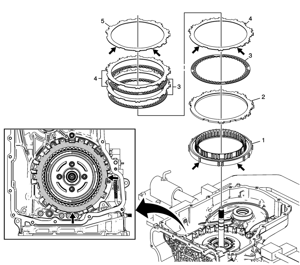
1 |
Low and Reverse Clutch Assembly (OWC) Note:
|
|
2 |
Low and Reverse Clutch Backing Plate |
|
3 |
Low and Reverse Clutch Plate Assembly (Qty: 3) |
|
4 |
Low and Reverse Clutch Plate (Qty: 3) Note: With the valve body face at the 6 o?lock position, align the large flat areas of the low and reverse clutch plate between the 2 o?lock and 5 o?lock position. |
|
5 |
Low and Reverse Clutch Apply (Waved) Plate Note:
|
 Low and Reverse and 1-2-3-4 Clutch Housing, and 1-2-3-4 Clutch Plate Installation
(6T40/45/50)
Low and Reverse and 1-2-3-4 Clutch Housing, and 1-2-3-4 Clutch Plate Installation
(6T40/45/50)
Low and Reverse and 1-2-3-4 Clutch Housing, and 1-2-3-4 Clutch Plate
Installation
Callout
Component Name
1
Low and Re ...
 Low and Reverse and 1-2-3-4 Clutch Housing, Low and Reverse Clutch Assembly,
Output Sun Gear, and 2-6 Clutch Plate Disassemble (Gen 1)
Low and Reverse and 1-2-3-4 Clutch Housing, Low and Reverse Clutch Assembly,
Output Sun Gear, and 2-6 Clutch Plate Disassemble (Gen 1)
Low and Reverse and 1-2-3-4 Clutch Housing, Low and Reverse Clutch
Assembly, Output Sun Gear, and 2-6 Clutch Plate Disassemble
Callout
Component Name ...
Other materials:
Special Tools
Illustration
Tool Number/ Description
BO-594-A
Hand Rivet Tongs
...
Turbocharger Replacement
Special Tools
EN-49942 Holding Wrench
For equivalent regional tools, refer to Special Tools.
Removal Procedure
Disconnect battery negative cable. Refer to Battery Negative Cable Disconnection
and Connection.
Drain the cooling system. Refer to Cooling System Draining and Fi ...
Basic information
The Nissan Armada is equipped with an advanced automatic brake hold function
designed to enhance driving convenience in stop-and-go traffic conditions. This
system automatically maintains braking force when the vehicle comes to a complete
stop, such as at traffic lights or intersections, allow ...

0.0063