Chevrolet Sonic Repair Manual: Main Shaft Disassemble (Gen 1)
| Table 1: | 1st Gear Removal |
| Table 2: | 1st Gear Blocking Rings Removal |
| Table 3: | 1st and 2nd Gear Synchronizer Hub Retaining Ring Removal |
| Table 4: | 1st and 2nd Gear Synchronizer Hub and 2nd Gear Removal |
| Table 5: | 2nd Gear Bearing Removal |
| Table 6: | 3rd Gear Removal |
| Table 7: | 3rd and 4th Gear Synchronizer Hub Retaining Ring Removal |
| Table 8: | 3rd and 4th Gear Thrust Washer Removal |
| Table 9: | 3rd and 4th Gear Synchronizer Hub and 4th Gear Removal |
| Table 10: | 4th Gear Bearing Removal |
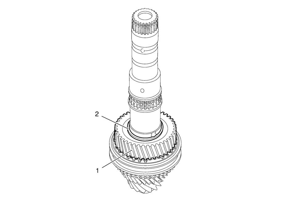
- 1st Gear Removal
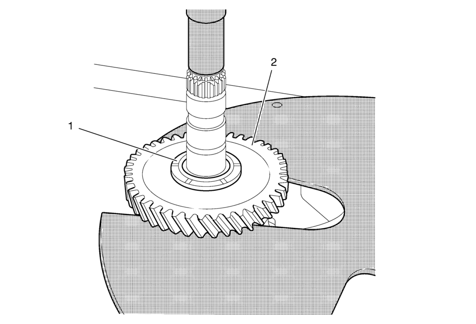
1st Gear Removal Callout
Component Name
Preliminary Procedure
A hydraulic press is required to complete procedure. Prepare hydraulic press for procedure.
1
1st Gear Thrust Washer
Special Tools- DT-307-B Remover Plate
- DT-736 Clutch Arbor
2
1st Gear
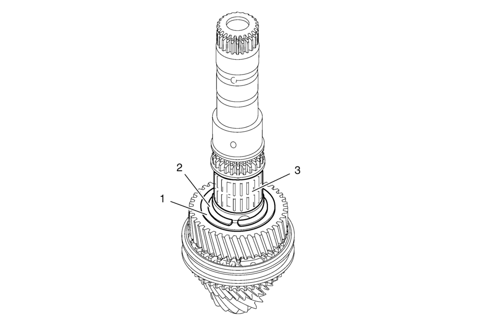
- 1st Gear Blocking Rings Removal
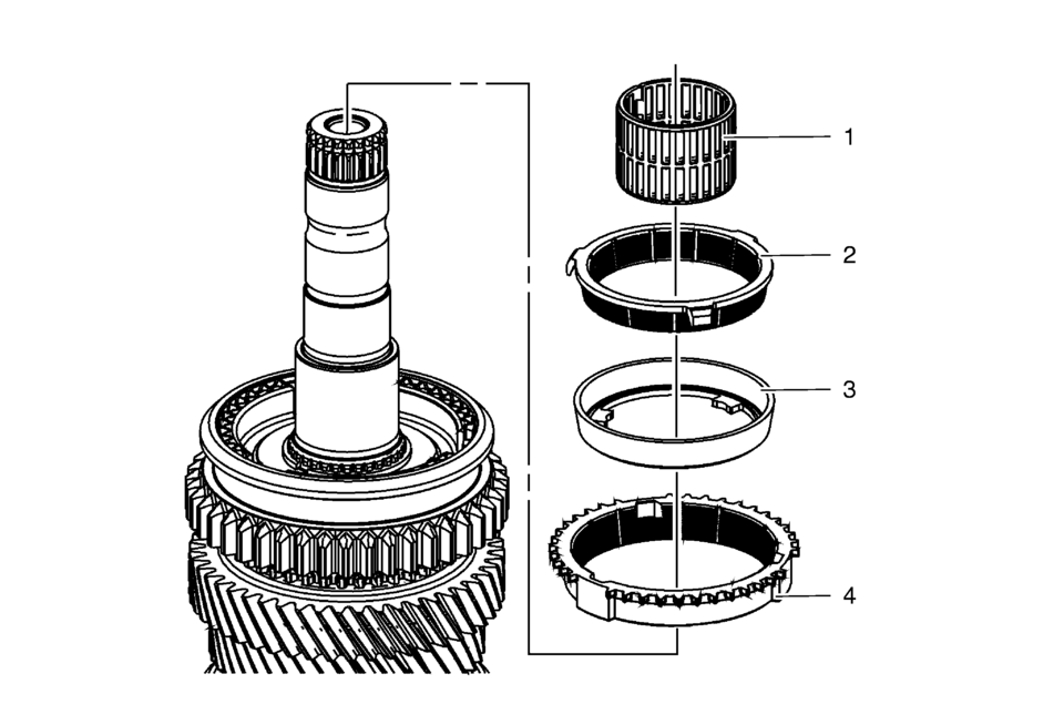
1st Gear Blocking Rings Removal Callout
Component Name
1
1st Gear Bearing
2
1st Gear Inner Blocking Ring
3
1st Gear Intermediate Blocking Ring
4
1st Gear Outer Blocking Ring
- 1st and 2nd Gear Synchronizer Hub Retaining Ring Removal
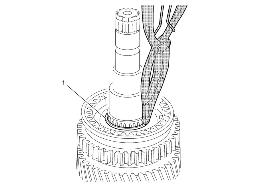
1st and 2nd Gear Synchronizer Hub Retaining Ring Removal Callout
Component Name
1
1st and 2nd Gear Synchronizer Hub Retaining Ring
Special Tools
GE-8059 Snap Ring Pliers
- 1st and 2nd Gear Synchronizer Hub and 2nd Gear Removal
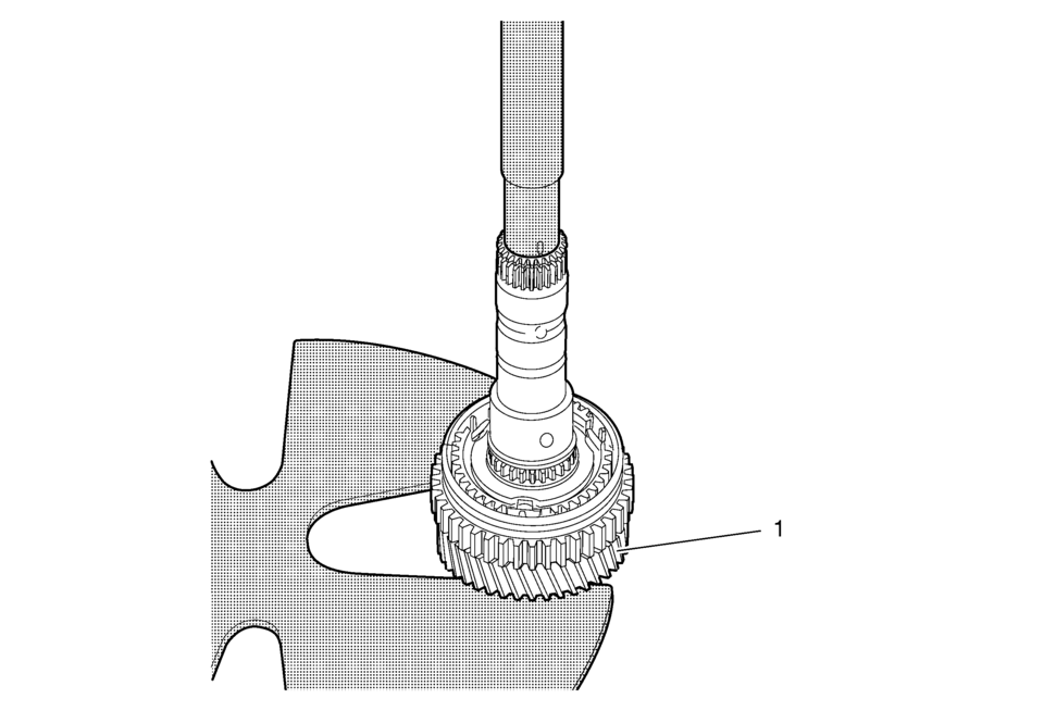
1st and 2nd Gear Synchronizer Hub and 2nd Gear Removal Callout
Component Name
Preliminary Procedure
A hydraulic press is required to complete procedure. Prepare hydraulic press for procedure.
1
2nd Gear
Special Tools- DT-307-B Remover Plate
- DT-736 Clutch Arbor
- 2nd Gear Bearing Removal
2nd Gear Bearing Removal Callout
Component Name
1
1st and 2nd Gear Synchronizer Hub Retaining Ring
2
2nd and 3rd Gear Thrust Washer
3
2nd Gear Bearing
- 3rd Gear Removal
3rd Gear Removal Callout
Component Name
1
3rd Gear
2
3rd Gear Bearing
- 3rd and 4th Gear Synchronizer Hub Retaining Ring Removal
3rd and 4th Gear Synchronizer Hub Retaining Ring Removal Callout
Component Name
1
3rd and 4th Gear Synchronizer Hub Retaining
Special Tools
GE-8059 Snap Ring Pliers
- 3rd and 4th Gear Thrust Washer Removal
3rd and 4th Gear Thrust Washer Removal Callout
Component Name
1
3rd and 4th Gear Synchronizer Hub Retaining Ring
Special Tools
GE-8059 Snap Ring Pliers
- 3rd and 4th Gear Synchronizer Hub and 4th Gear Removal
3rd and 4th Gear Synchronizer Hub and 4th Gear Removal Callout
Component Name
Preliminary Procedure
A hydraulic press is required to complete procedure. Prepare hydraulic press for procedure.
1
3rd and 4th Gear Synchronizer Hub
Special Tools- DT-307-B Remover Plate
- DT-736 Clutch Arbor
2
4th Gear
- 4th Gear Bearing Removal
4th Gear Bearing Removal Callout
Component Name
1
4th Gear Bearing
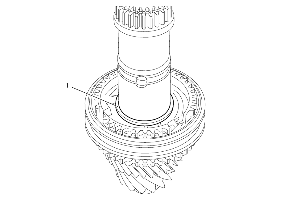
 Main Shaft Assemble (Gen 2)
Special Tools
3-0207944 Main Shaft Tapered Bearing Insert Tool
For equivalent regional tools, refer to Special Tools.
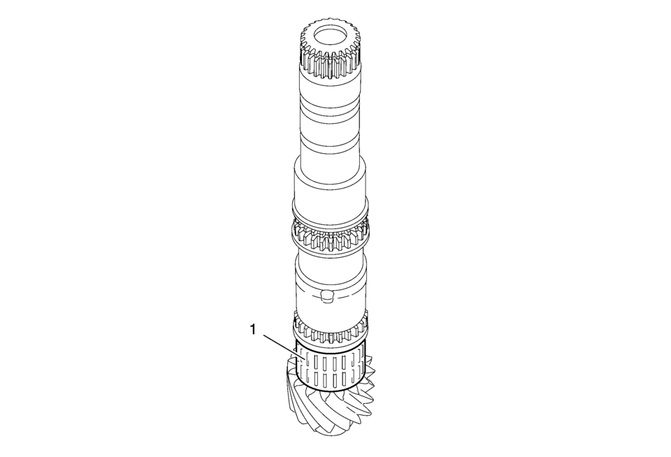
Install the 4th gear bearing assembly (1).
in!i.l.i-if
...
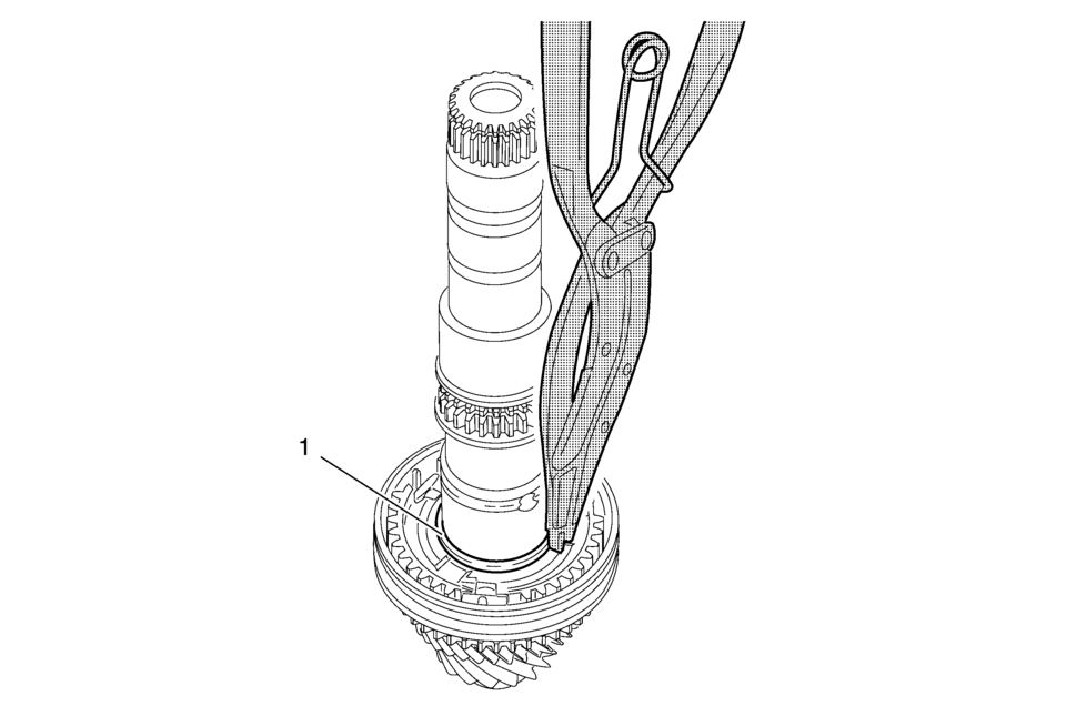
 Main Shaft Disassemble (Gen 2)
Special Tools
69604356 Gear Pullers
For equivalent regional tools, refer to Special Tools.
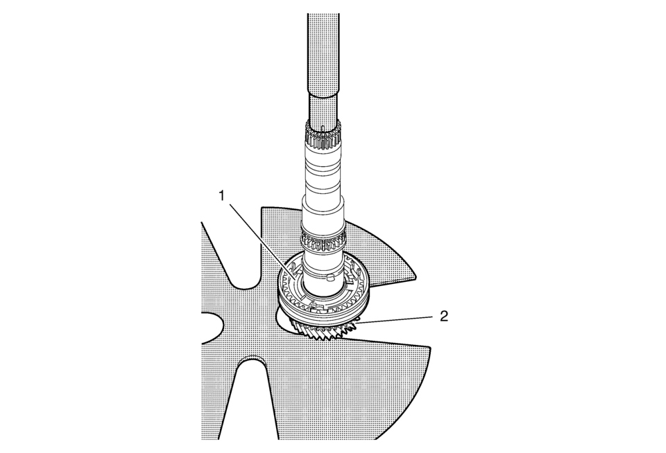
Remove the 1st gear thrust washer (1) and the 1st gear (2)
using 69604356 pull ...
Other materials:
Additional Factors Affecting System Operation
Safety belts help keep the passenger in position on the seat during vehicle maneuvers
and braking, which helps the passenger sensing system maintain the passenger airbag
status. See “Safety Belts” and “Child Restraints” in the Index for additional information
about the importance of pr ...
Settings
Basic information
The Settings mode in the Nissan Armada provides drivers with a comprehensive
interface for customizing both the vehicle information display and various system
configurations. Through this menu, users can tailor the Nissan Armada driving experience
according to personal prefe ...
Air cleaner
To access the air filter in your Nissan Armada, release the retaining clips 1
and carefully lift the air cleaner housing upward 2.
The air filter element in the Nissan Armada is designed for single use and should
not be cleaned or reused. Replace it strictly according to the recommended mai ...

0.0792