Chevrolet Sonic Repair Manual: Master Cylinder Replacement
- Removal Procedure
-
Warning:
Refer to Brake Fluid Irritant Warning.
Caution:
Refer to Brake Fluid Effects on Paint and Electrical Components Caution.
- Place the ignition switch in the OFF position.
- Remove the battery. Refer to Battery Replacement.
- Disconnect the brake fluid level indicator switch electrical connector.
- Using a suitable suction device, remove and properly discard the brake fluid from the brake master cylinder reservoir.
- On manual transmission equipped vehicles, disconnect the clutch master cylinder reservoir hose. Refer to Clutch Master Cylinder Reservoir Hose Replacement
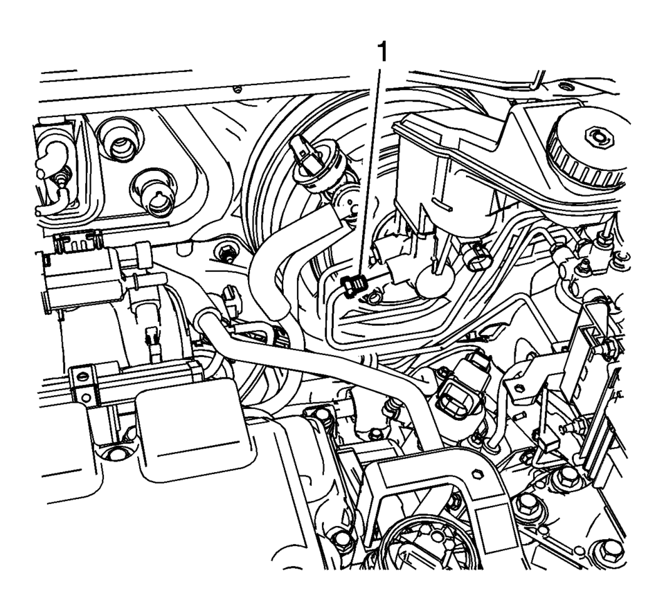
- Disconnect the master cylinder secondary brake pipe fitting (1).
- Cap the brake pipe fitting and plug the master cylinder outlet port to prevent brake fluid loss and contamination.
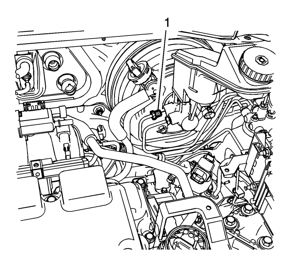
- Disconnect the master cylinder primary brake pipe fitting (1).
- Cap the brake pipe fitting and plug the master cylinder outlet port to prevent brake fluid loss and contamination.
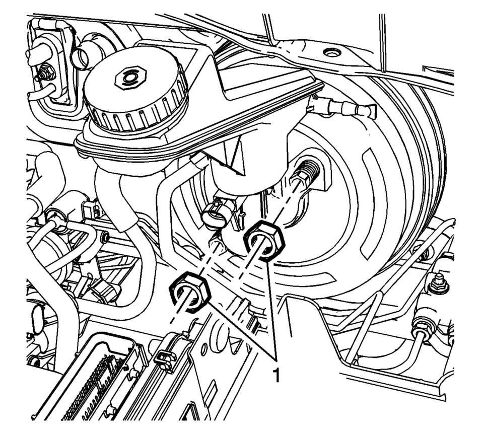
- Remove the master cylinder nuts (1).
- Remove the brake master cylinder.
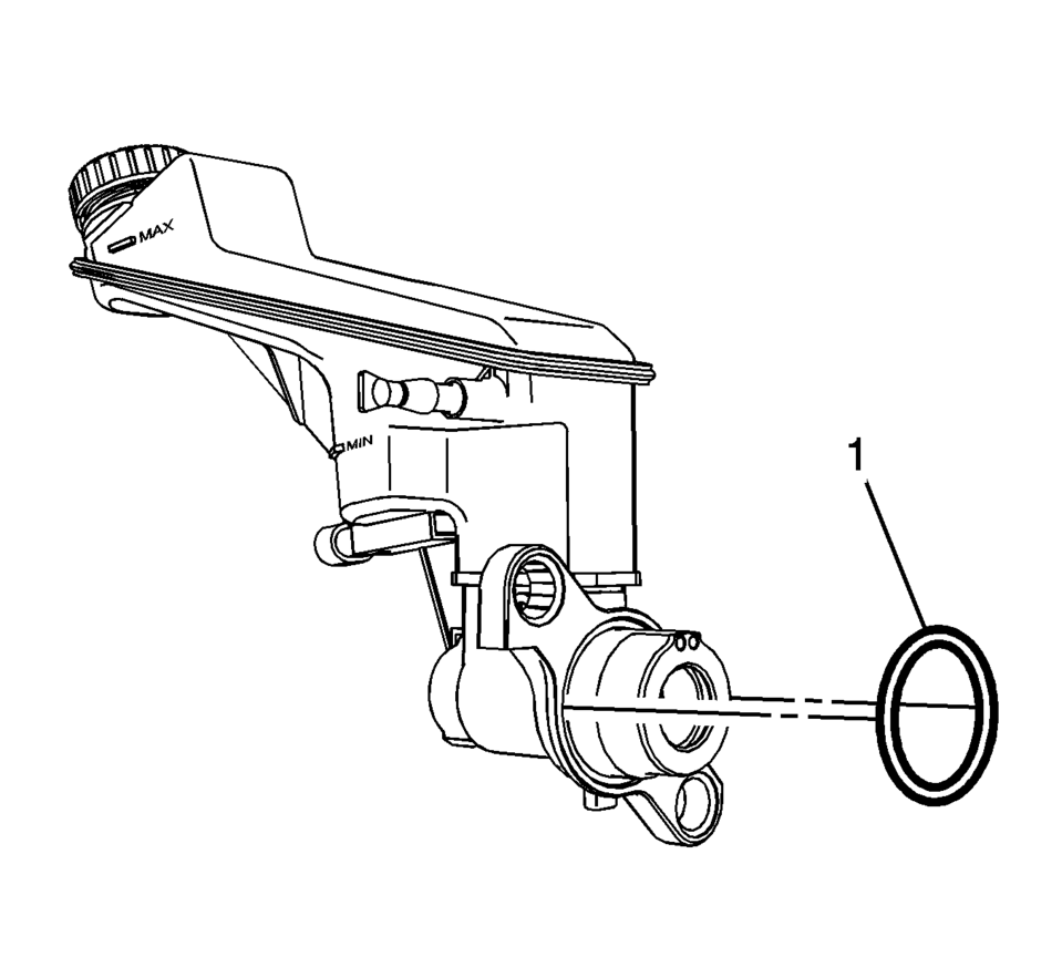
- Remove the master cylinder seal (1).
- Inspect the master cylinder seal for damage or deterioration and replace, if necessary.
- Remove the brake fluid level indicator switch, if necessary. Refer to Brake Fluid Level Indicator Switch Replacement.
- Remove the master cylinder reservoir, if necessary. Refer to Master Cylinder Reservoir Replacement.
- Installation Procedure
-
- Install the master cylinder reservoir, if removed. Refer to Master Cylinder Reservoir Replacement.
- Bench bleed the master cylinder. Refer to Master Cylinder Bench Bleeding.
- Install the brake fluid level indicator switch, if removed. Refer to Brake Fluid Level Indicator Switch Replacement.
- Install the master cylinder seal (1).
- Install the master cylinder to the power vacuum brake booster.
- Install the master cylinder nuts (1) and tighten to 50 Y (37 lb ft)
.
- Connect the master cylinder primary brake pipe fitting (1) and tighten
to 18 Y (13 lb ft)
.
- Connect the master cylinder secondary brake pipe fitting (1) and tighten
to 18 Y (13 lb ft)
.
- On manual transmission equipped vehicles, connect the clutch master cylinder reservoir hose. Refer to Clutch Master Cylinder Reservoir Hose Replacement
- Connect the brake fluid level indicator switch electrical connector.
- Install the battery. Refer to Battery Replacement.
- Bleed the hydraulic brake system. Refer to Hydraulic Brake System Bleeding.
Caution:
Refer to Fastener Caution.
 Master Cylinder Bench Bleeding
Warning: Refer to Brake Fluid Irritant Warning.
Caution: Refer to Brake Fluid Effects on Paint and Electrical
Components Caution.
Secure the mounting flange of the bra ...
 Special Tools
Illustration
Tool Number/ Description
CH 28662
J 28662
Brake Pedal Effort Gauge
...
Other materials:
Rear Side Door Window Switch Bezel Replacement
Rear Side Door Window Switch Bezel Replacement
Callout
Component Name
Preliminary Procedure
Remove the rear side door trim. Refer to Rear Side Door Trim Replacement.
1
Rear Side Door Pull Handle ...
Front Seat Belt Buckle Replacement
Front Seat Belt Buckle Replacement
Callout
Component Name
Preliminary Procedures
Remove the front seat. Refer to Driver or Passenger Seat Removal and
Installation.
1
Driver or Passenger Seat Bel ...
Wheel Replacement
Replace any wheel that is bent, cracked, or badly rusted or corroded. If wheel
nuts keep coming loose, the wheel, wheel bolts, and wheel nuts should be replaced.
If the wheel leaks air, replace it. Some aluminum wheels can be repaired. See your
dealer if any of these conditions exist.
Your d ...

0.0065