Chevrolet Sonic Repair Manual: Rear End Panel Replacement
- Removal Procedure
-
- Disable the SIR System. Refer to SIR Disabling and Enabling.
- Disconnect the negative battery cable. Refer to Battery Negative Cable Disconnection and Connection.
- Remove all related panels and components.
- Visually inspect the damage. Repair as much of the damage as possible.
- Remove the sealers and anti-corrosion materials from the repair area, as necessary. Refer to Anti-Corrosion Treatment and Repair.
- Locate and mark all the necessary factory welds of the body rear end panel.
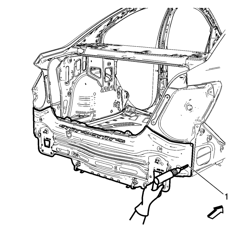
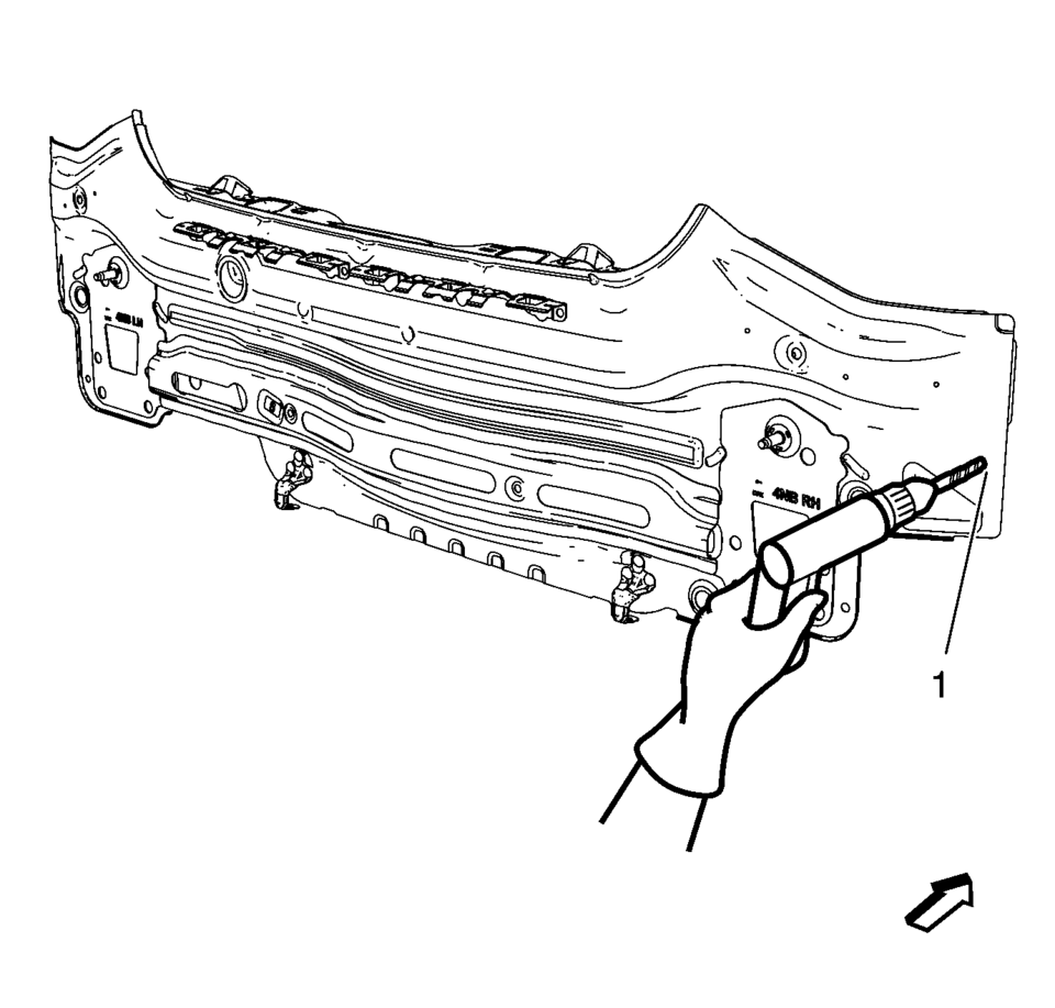
- Drill all factory welds (1).
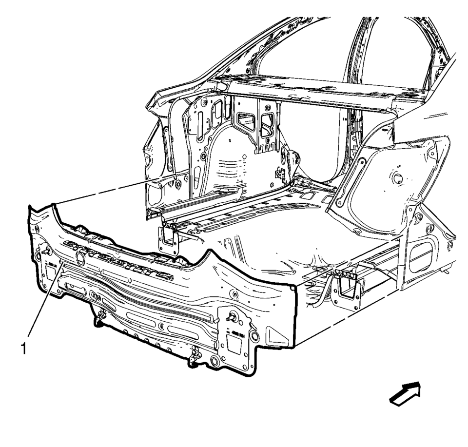
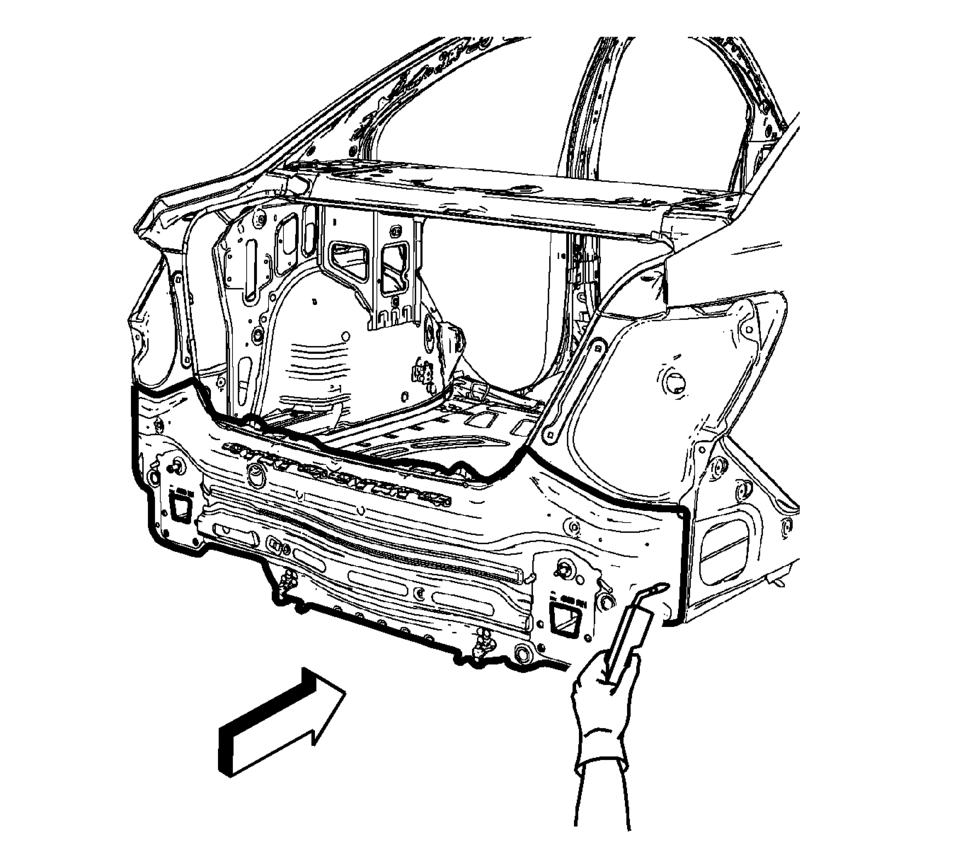
- Remove the body rear end panel (1).
Warning:
Refer to Approved Equipment for Collision Repair Warning.
Warning:
Refer to Glass and Sheet Metal Handling Warning.
Note:
The rear end lower panel reinforcement extension is made of Ultra High Strength Dual Phase Steel and should be replaced only at factory joints. Repairing or sectioning of this part is not recommended. Refer to Ultra High Strength Dual Phase Steel.
Note:
Note the number and location of welds for installation of the service assembly.
- Installation Procedure
-
- Drill 8?€‰mm (5/16?€‰in)
holes for plug welding along the edges of the body rear end panel (1) as noted from the original panel.
- Clean and prepare the attaching surfaces for welding.
- Position the body rear end panel on the vehicle (1).
- Verify the fit of the body rear end panel.
- Clamp the body rear end panel into position.
- Plug weld accordingly.
- Apply the sealers and anti-corrosion materials to the repair area, as necessary. Refer to Anti-Corrosion Treatment and Repair.
- Paint the repaired area. Refer to Basecoat/Clearcoat Paint Systems.
- Install all related panels and components.
- Connect the negative battery cable. Refer to Battery Negative Cable Disconnection and Connection.
- Enable the SIR system. Refer to SIR Disabling and Enabling.
Note:
If the location of the original plug weld holes can not be determined, space the plug weld holes every 40?€‰mm (1 1/2?€‰in)
.
- Drill 8?€‰mm (5/16?€‰in)
 Front Fender Replacement
Front Fender Replacement
Callout
Component Name
Preliminary Procedures
Remove the front bumper fascia. Refer to Front Bumper Fascia ...
 Roof Panel Joint Finish Molding Replacement
Roof Panel Joint Finish Molding Replacement
Callout
Component Name
Caution: Refer to Exterior Trim Emblem Removal Caution.
...
Other materials:
HVAC System Control Module Programming and Setup
Note:
DO NOT program a control module unless directed to by a service procedure
or a service bulletin. If the control module is not properly configured
with the correct calibration software, the control module will not control
all of the vehicle features properly.
Ensure th ...
Rear Brake Hose Replacement (Body to Axle - Disc Brake)
Removal Procedure
Warning: Refer to Brake Dust Warning.
Warning: Refer to Brake Fluid Irritant Warning.
Raise and support the vehicle. Refer to Lifting and Jacking the Vehicle.
Remove the tire and wheel assembly. Refer to Tire and Wheel Removal
and Install ...
Evaporative Emission Canister Replacement
Removal Procedure
Raise and support the vehicle. Refer to Lifting and Jacking the Vehicle.
Remove the EVAP canister cover fasteners (1) and cover (2).
Warning: Do not breathe the air through the EVAP component
tubes or hoses. The fuel vapors inside t ...

0.0064